Product Description
Stainless Steel Coupling Gear Rigid Roller Chain Fluid Tyre Grid Jaw Spider HRC Nm Motor Flange Gear Pump Rubber Spline Shaft Flexible Universal Joint Coupling
Product Description
Main products
Coupling refers to a device that connects 2 shafts or shafts and rotating parts, rotates together during the transmission of motion and power, and does not disengage under normal conditions. Sometimes it is also used as a safety device to prevent the connected parts from bearing excessive load, which plays the role of overload protection.
Couplings can be divided into rigid couplings and flexible couplings.
Rigid couplings do not have buffering property and the ability to compensate the relative displacement of 2 axes. It is required that the 2 axes be strictly aligned. However, such couplings are simple in structure, low in manufacturing cost, convenient in assembly and disassembly, and maintenance, which can ensure that the 2 axes are relatively neutral, have large transmission torque, and are widely used. Commonly used are flange coupling, sleeve coupling and jacket coupling.
Flexible coupling can also be divided into flexible coupling without elastic element and flexible coupling with elastic element. The former type only has the ability to compensate the relative displacement of 2 axes, but cannot cushion and reduce vibration. Common types include slider coupling, gear coupling, universal coupling and chain coupling; The latter type contains elastic elements. In addition to the ability to compensate the relative displacement of 2 axes, it also has the functions of buffering and vibration reduction. However, due to the strength of elastic elements, the transmitted torque is generally inferior to that of flexible couplings without elastic elements. Common types include elastic sleeve pin couplings, elastic pin couplings, quincunx couplings, tire type couplings, serpentine spring couplings, spring couplings, etc
Coupling performance
1) Mobility. The movability of the coupling refers to the ability to compensate the relative displacement of 2 rotating components. Factors such as manufacturing and installation errors between connected components, temperature changes during operation and deformation under load all put CHINAMFG requirements for mobility. The movable performance compensates or alleviates the additional load between shafts, bearings, couplings and other components caused by the relative displacement between rotating components.
(2) Buffering. For the occasions where the load is often started or the working load changes, the coupling shall be equipped with elastic elements that play the role of cushioning and vibration reduction to protect the prime mover and the working machine from little or no damage.
(3) Safe, reliable, with sufficient strength and service life.
(4) Simple structure, easy to assemble, disassemble and maintain.
How to select the appropriate coupling type
The following items should be considered when selecting the coupling type.
1. The size and nature of the required transmission torque, the requirements for buffering and damping functions, and whether resonance may occur.
2. The relative displacement of the axes of the 2 shafts is caused by manufacturing and assembly errors, shaft load and thermal expansion deformation, and relative movement between components.
3. Permissible overall dimensions and installation methods, and necessary operating space for assembly, adjustment and maintenance. For large couplings, they should be able to be disassembled without axial movement of the shaft.
In addition, the working environment, service life, lubrication, sealing, economy and other conditions should also be considered, and a suitable coupling type should be selected by referring to the characteristics of various couplings.
If you cannot determine the type, you can contact our professional engineer
Related products
Company Profile
Our Equipments
Main production equipment:
Large lathe, surface grinder, milling machine, gear shaper, spline milling machine, horizontal broaching machine, gear hobbing machine, shaper, slotting machine, bench drilling machine, radial drilling machine, boring machine, band sawing machine, horizontal lathe, end milling machine, crankshaft grinder, CNC milling machine, casting equipment, etc.
Inspection equipment:
Dynamic balance tester, high-speed intelligent carbon and sulfur analyzer, Blochon optical hardness tester, Leeb hardness tester, magnetic yoke flaw detector, special detection, modular fixture (self-made), etc.
Machining equipments
Heat equipment
Our Factory
Application – Photos from our partner customers
Company Profile
Our leading products are mechanical transmission basic parts – couplings, mainly including universal couplings, drum gear couplings, elastic couplings and other 3 categories of more than 30 series of varieties. It is widely used in metallurgical steel rolling, wind power, hydropower, mining, engineering machinery, petrochemical, lifting, paper making, rubber, rail transit, shipbuilding and marine engineering and other industries.
Our factory takes the basic parts of national standards as the benchmark, has more than 40 years of coupling production experience, takes “scientific management, pioneering and innovation, ensuring quality and customer satisfaction” as the quality policy, and aims to continuously provide users with satisfactory products and services. The production is guided by reasonable process, and the ISO9001:2015 quality management system standard is strictly implemented. We adhere to the principle of continuous improvement and innovation of coupling products. In recent years, it has successfully developed 10 national patent products such as SWF cross shaft universal coupling, among which the double cross shaft universal joint has won the national invention patent, SWF cross shaft universal coupling has won the new product award of China’s general mechanical parts coupling industry and the ZHangZhoug Province new product science and technology project.
Our factory has strong technical force, excellent process equipment, complete professional production equipment, perfect detection means, excellent after-sales service, various products and complete specifications. At the same time, we can provide the design and manufacturing of special non-standard products according to the needs of users. Our products sell well at home and abroad, and are trusted by the majority of users. We sincerely welcome friends from all walks of life at home and abroad to visit and negotiate for common development.p
Maintenance Requirements for Gear Couplings
Gear couplings, like any mechanical component, require regular maintenance to ensure optimal performance, reliability, and longevity. Proper maintenance can help prevent unexpected failures and downtime, leading to cost savings and increased productivity. Here are the key maintenance requirements for gear couplings:
- Lubrication: Regular and proper lubrication is essential for gear couplings. The coupling’s gear teeth and mating surfaces should be adequately lubricated to minimize friction and wear. The lubrication interval and type of lubricant used depend on the application, load, and operating conditions. It is crucial to follow the manufacturer’s recommendations for lubrication intervals and the appropriate lubricant to use.
- Inspections: Routine inspections should be performed to check for signs of wear, misalignment, or damage. Visual inspections can help detect any abnormalities, such as pitting, scoring, or corrosion on the gear teeth. Additionally, inspections can identify any misalignment issues that may need to be addressed to prevent further damage.
- Torque Monitoring: Monitoring the torque transmitted through the coupling can help identify any abnormal increases that might indicate a problem in the system. Sudden changes in torque levels could signal misalignment or other issues that need attention.
- Alignment Checks: Regularly checking and correcting shaft alignment is crucial for the proper functioning of gear couplings. Misalignment can lead to increased wear and premature failure of the coupling. Proper alignment reduces the stress on the coupling and connected equipment.
- Temperature Monitoring: Monitoring the operating temperature of the coupling can provide insights into potential problems. Abnormally high temperatures could indicate insufficient lubrication or other issues that need investigation.
- Coupling Removal and Cleaning: Periodically removing the coupling for cleaning and inspection of internal components can be beneficial, especially in harsh or dirty environments. This allows for a more thorough inspection and helps maintain the coupling’s performance.
- Replacement of Worn Components: If any components of the gear coupling, such as seals or gaskets, are worn or damaged, they should be replaced promptly to maintain the coupling’s integrity and prevent leaks.
- Proper Storage: If the coupling is temporarily removed from service or stored, it should be stored in a clean and dry environment to prevent corrosion and damage to the components.
It is essential to follow the manufacturer’s maintenance guidelines and recommendations for the specific gear coupling model being used. Regular maintenance and adherence to proper procedures can help extend the service life of gear couplings and ensure reliable and efficient operation in the mechanical system.


editor by CX 2023-10-07
China Standard Flange Cast Iron Coupling Steel Universal Joint Cardan Pump Rubber Motor Disc Curved Tooth Flex Rigid Drive Shaft Nm Yox Fluid Jaw Flexible Chain Gear Couplings gear coupling
Product Description
Flange Cast Iron Coupling Steel Universal Joint Cardan Pump Rubber Motor Disc CHINAMFG Flex Rigid Drive Shaft NM yox Fluid Jaw Flexible Chain Gear Couplings
Manufacturer of Couplings, Fluid Coupling, JAW Coupling, can interchange and replacement of lovejoy coupling and so on.
A coupling can interchange and replacement of lovejoy coupling is a device used to connect 2 shafts together at their ends for the purpose of transmitting power. The primary purpose of couplings is to join 2 pieces of rotating equipment while permitting some degree of misalignment or end movement or both. In a more general context, a coupling can also be a mechanical device that serves to connect the ends of adjacent parts or objects. Couplings do not normally allow disconnection of shafts during operation, however there are torque limiting couplings which can slip or disconnect when some torque limit is exceeded. Selection, installation and maintenance of couplings can lead to reduced maintenance time and maintenance cost.
Coupling is a jaw type coupling that works for a variety of light duty to heavy duty motors used in electric power transmission.
This is 1 of our safest types of products. The reason being that these couplings work even when the elastomer fails and there is no metal to metal contact.
They perform in well-standing oil, grease, moisture, sand, and dirt and nearly 850,000 bore combinations that can be customised as per the customer’s needs.
They are used in light-weight, medium, or heavy electrical motors and devices for power transmission through internal combustion.
Production workshop:
Company information:
Selection of Gear Couplings for Specific Applications
Choosing the appropriate gear coupling for a specific application involves considering several factors to ensure optimal performance and reliability. Here are the key steps in the selection process:
- Identify Application Requirements: Understand the specific requirements of the application, including the torque and speed requirements, operating conditions, and the amount of angular and axial misalignment expected in the system.
- Calculate Torque and Speed: Determine the required torque and speed ratings for the gear coupling based on the power transmission needs of the application. Consider both peak and continuous torque requirements.
- Consider Misalignment: Evaluate the amount and type of misalignment that the gear coupling needs to accommodate. Different gear coupling designs have varying degrees of misalignment capabilities, so it’s essential to choose one that can handle the expected misalignment in the system.
- Check Space Constraints: Consider the available space for installing the gear coupling. Some applications may have limited space, requiring compact or specially designed couplings to fit properly.
- Assess Environmental Conditions: Determine if the application involves exposure to extreme temperatures, corrosive substances, or other harsh environmental factors. Select a gear coupling made from materials that can withstand the specific environmental conditions.
- Consider Maintenance Requirements: Evaluate the maintenance needs of the gear coupling. Some designs may require more frequent maintenance than others. For applications where regular maintenance is challenging, consider maintenance-free gear coupling options.
- Check Industry Standards and Certifications: Ensure that the selected gear coupling meets relevant industry standards and certifications to guarantee quality and safety.
- Consult with Experts: If needed, seek guidance from coupling manufacturers or engineering experts who can provide valuable insights and recommendations based on their experience and expertise.
By carefully considering these factors and understanding the specific demands of the application, you can select the most suitable gear coupling that will provide reliable and efficient power transmission while minimizing the risk of premature failure or downtime.
editor by CX 2023-10-03
China supplier Motor Coupling Reducer Couples Necklace Pair Bathing Suit Bracelet Stainless Magnetic Conduit Hydraulic Matching Outfit Gear Coupling Quick Release Flexible gear coupling
Product Description
Motor coupling reducer couples necklace pair bathing suit bracelet stainless magnetic conduit hydraulic matching outfit gear coupling quick release flexible
Application of Reducer Coupling
A reducer coupling is a pipe fitting that is used to connect 2 pipes of different sizes. It is a type of adapter that allows for a smooth transition between the 2 pipes. Reducer couplings are available in a variety of sizes and materials, and they can be used in a variety of applications.
Some of the most common applications for reducer couplings include:
- Connecting pipes of different sizes: Reducer couplings are used to connect pipes of different sizes, such as when you need to connect a smaller pipe to a larger pipe. This is a common application in plumbing, HVAC, and other types of construction.
- Changing the direction of a pipe: Reducer couplings can also be used to change the direction of a pipe. This is a common application in plumbing, as it allows you to route pipes in a way that is both efficient and aesthetically pleasing.
- Repairing a damaged pipe: Reducer couplings can also be used to repair a damaged pipe. This is a common application in plumbing, as it allows you to repair a pipe without having to replace the entire pipe.
Reducer couplings are a versatile and useful tool that can be used in a variety of applications. They are an easy and affordable way to connect pipes of different sizes, change the direction of a pipe, or repair a damaged pipe.
Here are some additional tips for using reducer couplings:
- Make sure that the reducer coupling is the correct size for the pipes that you are connecting.
- Use a pipe joint compound to seal the reducer coupling.
- Tighten the reducer couplings by hand, and then use a wrench to tighten them further.
- Do not overtighten the reducer couplings, as this can damage the pipes.
By following these tips, you can safely and effectively use reducer couplings to connect pipes of different sizes.
What Industries Commonly Use Gear Couplings for Power Transmission?
Gear couplings are widely used in various industries for power transmission due to their ability to transmit high torque loads and accommodate misalignments. Some of the industries that commonly utilize gear couplings include:
- Steel Industry: Gear couplings are extensively used in the steel industry for connecting heavy-duty equipment like rolling mills, continuous casting machines, and other steel processing machinery.
- Mining and Quarrying: In mining and quarrying applications, gear couplings are employed to transmit power in conveyor systems, crushers, and heavy excavating machinery.
- Pulp and Paper: The pulp and paper industry uses gear couplings in machines like paper mills, pulp refiners, and stock preparation equipment.
- Marine: Gear couplings are utilized in marine propulsion systems, providing a reliable connection between the engine and the propeller shafts.
- Oil and Gas: Gear couplings find use in the oil and gas industry for connecting pumps, compressors, and other equipment used in upstream and downstream operations.
- Power Generation: Gear couplings are employed in power plants to connect generators, turbines, and other rotating equipment.
- Automotive: Gear couplings are used in automotive applications, particularly in heavy-duty vehicles and machinery like off-road vehicles, construction equipment, and agricultural machinery.
- Chemical and Petrochemical: In chemical processing plants, gear couplings are employed in agitators, mixers, and various equipment where power transmission is crucial.
- Cement and Aggregate: Gear couplings are used in cement plants and aggregate processing equipment for power transmission in crushers, kilns, and conveyors.
These are just a few examples, and gear couplings can be found in various other industries where reliable power transmission is essential. Their robust design and ability to withstand harsh operating conditions make them a popular choice for heavy-duty applications across different sectors.
editor by CX 2023-09-12
China supplier Flange Cast Iron Coupling Steel Universal Joint Cardan Pump Rubber Motor Disc Curved Tooth Flex Rigid Drive Shaft Nm Yox Fluid Jaw Flexible Chain Gear Couplings gear coupling
Product Description
Flange Cast Iron Coupling Steel Universal Joint Cardan Pump Rubber Motor Disc CZPT Flex Rigid Drive Shaft NM yox Fluid Jaw Flexible Chain Gear Couplings
Manufacturer of Couplings, Fluid Coupling, JAW Coupling, can interchange and replacement of lovejoy coupling and so on.
A coupling can interchange and replacement of lovejoy coupling is a device used to connect 2 shafts together at their ends for the purpose of transmitting power. The primary purpose of couplings is to join 2 pieces of rotating equipment while permitting some degree of misalignment or end movement or both. In a more general context, a coupling can also be a mechanical device that serves to connect the ends of adjacent parts or objects. Couplings do not normally allow disconnection of shafts during operation, however there are torque limiting couplings which can slip or disconnect when some torque limit is exceeded. Selection, installation and maintenance of couplings can lead to reduced maintenance time and maintenance cost.
Coupling is a jaw type coupling that works for a variety of light duty to heavy duty motors used in electric power transmission.
This is 1 of our safest types of products. The reason being that these couplings work even when the elastomer fails and there is no metal to metal contact.
They perform in well-standing oil, grease, moisture, sand, and dirt and nearly 850,000 bore combinations that can be customised as per the customer’s needs.
They are used in light-weight, medium, or heavy electrical motors and devices for power transmission through internal combustion.
Production workshop:
Company information:
What Industries Commonly Use Gear Couplings for Power Transmission?
Gear couplings are widely used in various industries for power transmission due to their ability to transmit high torque loads and accommodate misalignments. Some of the industries that commonly utilize gear couplings include:
- Steel Industry: Gear couplings are extensively used in the steel industry for connecting heavy-duty equipment like rolling mills, continuous casting machines, and other steel processing machinery.
- Mining and Quarrying: In mining and quarrying applications, gear couplings are employed to transmit power in conveyor systems, crushers, and heavy excavating machinery.
- Pulp and Paper: The pulp and paper industry uses gear couplings in machines like paper mills, pulp refiners, and stock preparation equipment.
- Marine: Gear couplings are utilized in marine propulsion systems, providing a reliable connection between the engine and the propeller shafts.
- Oil and Gas: Gear couplings find use in the oil and gas industry for connecting pumps, compressors, and other equipment used in upstream and downstream operations.
- Power Generation: Gear couplings are employed in power plants to connect generators, turbines, and other rotating equipment.
- Automotive: Gear couplings are used in automotive applications, particularly in heavy-duty vehicles and machinery like off-road vehicles, construction equipment, and agricultural machinery.
- Chemical and Petrochemical: In chemical processing plants, gear couplings are employed in agitators, mixers, and various equipment where power transmission is crucial.
- Cement and Aggregate: Gear couplings are used in cement plants and aggregate processing equipment for power transmission in crushers, kilns, and conveyors.
These are just a few examples, and gear couplings can be found in various other industries where reliable power transmission is essential. Their robust design and ability to withstand harsh operating conditions make them a popular choice for heavy-duty applications across different sectors.
editor by CX 2023-08-31
China wholesaler Fluid Coupling Chain Jaw Flexible Flange Gear Rigid Spacer Motor Shaft Universal Half Reducer Spline Stainless Steel Elastomeric Coupling gear coupling
Product Description
Fluid Coupling Chain Jaw Flexible Flange Gear Rigid Spacer Motor Shaft Universal Half Reducer Spline Stainless Steel Elastomeric coupling
A fluid coupling is a torque converter used in mechanical power transmission systems to transmit torque from 1 rotating shaft to another. It consists of 2 halves, the impeller, and the runner, which are placed in a housing filled with a hydraulic fluid such as oil or water.
When one-half of the fluid coupling is rotated, it creates a fluid flow within the housing, which in turn causes the other half to rotate. The fluid coupling uses fluid dynamics principles to transmit torque between the 2 halves, with the amount of torque being proportional to the speed difference between the 2 shafts.
One of the key advantages of a fluid coupling is its ability to provide a smooth and gradual torque transfer between the 2 shafts, without any mechanical connection. This can help to reduce wear and tear on the equipment and improve overall system efficiency.
Fluid couplings are commonly used in various industrial applications, including mining, construction, and marine equipment. They are also used in automotive transmissions, where they can help provide a smooth and efficient torque transfer between the engine and the wheels.
Overall, a fluid coupling provides a reliable and efficient way to transmit torque between 2 rotating shafts, without any mechanical connection. With their ability to provide a smooth and gradual torque transfer, they are a popular choice for a wide range of industrial and automotive applications.
Selection of Gear Couplings for Specific Applications
Choosing the appropriate gear coupling for a specific application involves considering several factors to ensure optimal performance and reliability. Here are the key steps in the selection process:
- Identify Application Requirements: Understand the specific requirements of the application, including the torque and speed requirements, operating conditions, and the amount of angular and axial misalignment expected in the system.
- Calculate Torque and Speed: Determine the required torque and speed ratings for the gear coupling based on the power transmission needs of the application. Consider both peak and continuous torque requirements.
- Consider Misalignment: Evaluate the amount and type of misalignment that the gear coupling needs to accommodate. Different gear coupling designs have varying degrees of misalignment capabilities, so it’s essential to choose one that can handle the expected misalignment in the system.
- Check Space Constraints: Consider the available space for installing the gear coupling. Some applications may have limited space, requiring compact or specially designed couplings to fit properly.
- Assess Environmental Conditions: Determine if the application involves exposure to extreme temperatures, corrosive substances, or other harsh environmental factors. Select a gear coupling made from materials that can withstand the specific environmental conditions.
- Consider Maintenance Requirements: Evaluate the maintenance needs of the gear coupling. Some designs may require more frequent maintenance than others. For applications where regular maintenance is challenging, consider maintenance-free gear coupling options.
- Check Industry Standards and Certifications: Ensure that the selected gear coupling meets relevant industry standards and certifications to guarantee quality and safety.
- Consult with Experts: If needed, seek guidance from coupling manufacturers or engineering experts who can provide valuable insights and recommendations based on their experience and expertise.
By carefully considering these factors and understanding the specific demands of the application, you can select the most suitable gear coupling that will provide reliable and efficient power transmission while minimizing the risk of premature failure or downtime.
editor by CX 2023-08-18
China Hot selling Gfc-80X114 Manufacturer Flexible Clamp Style Shaft Spider Gear Motor Jaw Coupling gear coupling
Product Description
GFC-80X114 Manufacturer Flexible Clamp Style GFC Shaft Spider Gear Motor Jaw Coupling
GFC-80X114 Manufacturer Flexible Clamp Style GFC Shaft Spider Gear Motor Jaw Coupling
| model parameter | common bore diameter d1,d2 | ΦD | L | LF | LP | F | M | tightening screw torque (N.M) |
| GFC-14X22 | 3,4,5,6,6.35 | 14 | 22 | 14.3 | 6.6 | 5.0 | M2.5 | 1.0 |
| GFC-20×25 | 3,4,5,6,6.35,7,8,9,9.525,10 | 20 | 25 | 16.7 | 8.6 | 5.9 | M3 | 1.5 |
| GFC-20X30 | 3,4,5,6,6.35,7,8,9,9.525,10 | 20 | 30 | 19.25 | 8.6 | 5.9 | M3 | 1.5 |
| GFC-25X30 | 4,5,6,6.35,7,8,9,9.525,10,11,12 | 25 | 30 | 20.82 | 11.6 | 8.5 | M4 | 2.5 |
| GFC-25X34 | 4,5,6,6.35,7,8,9,9.525,10,11,12 | 25 | 34 | 22.82 | 11.6 | 8.5 | M4 | 2.5 |
| GFC-30×35 | 5,6,6.35,7,8,9,10,11,12,12.7,14,15,16 | 30 | 35 | 23 | 11.5 | 10 | M4 | 2.5 |
| GFC-30X40 | 5,6,6.35,7,8,9,10,11,12,12.7,14,15,16 | 30 | 40 | 25 | 11.5 | 10 | M4 | 2.5 |
| GFC-40X50 | 6,8,9,10,11,12,12.7,14,15,16,17,18,19,20,22,24 | 40 | 50 | 32.1 | 14.5 | 14 | M5 | 7 |
| GFC-40X55 | 6,8,9,10,11,12,12.7,14,15,16,17,18,19,20,22,24 | 40 | 55 | 34.5 | 14.5 | 14 | M5 | 7 |
| GFC-40X66 | 6,8,910,11,12,12.7,14,15,16,17,18,19,20,22,24 | 40 | 66 | 40 | 14.5 | 14 | M5 | 7 |
| GFC-55X49 | 10,11,12,12.7,14,15,16,17,18,19,20,22,24,25,28,30,32 | 55 | 49 | 32 | 16.1 | 13.5 | M6 | 12 |
| GFC-55X78 | 8,10,12,12.7,14,15,16,17,18,19,20,22,24,25,28,30,32 | 55 | 78 | 46.4 | 16.1 | 19 | M6 | 12 |
| GFC-65X80 | 14,15,16,17,18,19,20,22,24,25,28,30,32,35,38,40 | 65 | 80 | 48.5 | 17.3 | 14 | M8 | 20 |
| GFC-65X90 | 14,15,16,17,18,19,20,22,24,25,28,30,32,35,38,40 | 65 | 90 | 53.5 | 17.3 | 22.5 | M8 | 20 |
| GFC-80X114 | 19,20,22,24,25,28,30,32,35,38,40,42,45 | 80 | 114 | 68 | 22.5 | 16 | M8 | 20 |
| GFC-95X126 | 19,20,22,24,25,28,30,32,35,38,40,42,45,50,55 | 95 | 126 | 74.5 | 24 | 18 | M10 | 30 |
| model parameter | Rated torque (N.M)* |
allowable eccentricity (mm)* |
allowable deflection angle (°)* |
allowable axial deviation (mm)* |
maximum speed rpm |
static torsional stiffness (N.M/rad) |
moment of inertia (Kg.M2) |
Material of shaft sleeve | Material of shrapnel | surface treatment | weight (g) |
| GFC-14X22 | 5.0 | 0.1 | 1 | ±02 | 10000 | 50 | 1.0×10⁻⁶ | High strength aluminum alloy | Polyurethane imported from Germany | Anodizing treatment | 10 |
| GFC-20X25 | 5.0 | 0.1 | 1 | ±02 | 10000 | 50 | 1.0×10⁻⁶ | 15 | |||
| GFC-20X30 | 5.0 | 0.1 | 1 | ^02 | 10000 | 53 | 1.1×10⁻⁶ | 19 | |||
| GFC-25X30 | 10 | 0.1 | 1 | 10000 | 90 | 5.2X10⁻⁶ | 33 | ||||
| GFC-25X34 | 10 | 0.1 | 1 | £)2 | 10000 | 90 | 5.2×10⁻⁶ | 42 | |||
| GFC-30X35 | 12.5 | 0.1 | 1 | ±02 | 10000 | 123 | 6.2×10⁻⁶ | 50 | |||
| GFC-30×40 | 12.5 | 0.1 | 1 | 102 | 10000 | 123 | 6.2×10⁻⁶ | 60 | |||
| GFC-40X50 | 17 | 0.1 | 1 | 8000 | 1100 | 3.8×10⁻⁵ | 115 | ||||
| GFC-40X55 | 17 | 0.1 | 1 | ±02 | 8000 | 1100 | 3.8×10⁻⁵ | 127 | |||
| GFC-40X66 | 17 | 0.1 | 1 | 7000 | 1140 | 3.9×10⁻⁵ | 154 | ||||
| GFC-55X49 | 45 | 0.1 | 1 | ±02 | 6500 | 2350 | 1.6×10⁻³ | 241 | |||
| GFC-55X78 | 45 | 0.1 | 1 | 102 | 6000 | 2500 | 1.6×10⁻³ | 341 | |||
| GFC-65X80 | 108 | 0.1 | 1 | ±02 | 5500 | 4500 | 3.8×10⁻³ | 433 | |||
| GFC-65X90 | 108 | 0.1 | 1 | ±02 | 5500 | 4800 | 3.8×10⁻³ | 583 | |||
| GFC-80X114 | 145 | 0.1 | 1 | £)2 | 4500 | 5000 | 1.8×10⁻³ | 1650 | |||
| GFC-95X126 | 250 | 0.1 | 1 | ±02 | 4000 | 5000 | 2.0×10⁻³ | 1000 |
Types of Gear Coupling Designs
There are several types of gear coupling designs available, each with its own specific characteristics and applications. The main types of gear couplings are:
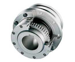
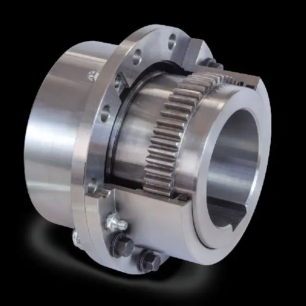
- Sleeve Gear Couplings: Sleeve gear couplings consist of two hubs with external gears and a center sleeve with internal gears. The hubs are mounted on the shaft ends, and the center sleeve connects the two hubs. This design allows for angular and axial misalignment while transmitting torque between the shafts. Sleeve gear couplings are suitable for general-purpose applications and offer easy maintenance.
- Continuous Sleeve Gear Couplings: Continuous sleeve gear couplings are an improved version of sleeve gear couplings. In this design, the center sleeve is extended to cover the entire length of the hubs, providing additional support and increasing torque capacity. The continuous sleeve design reduces the bending effect on the shafts and allows for higher torque transmission.
- Flanged Sleeve Gear Couplings: Flanged sleeve gear couplings are similar to continuous sleeve couplings but include flanges at the ends of the center sleeve. These flanges provide extra support and help maintain proper alignment between the shafts. Flanged sleeve gear couplings are commonly used in high-speed and heavy-duty applications.
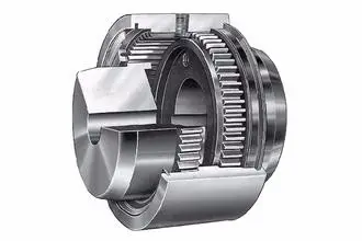
- Half Gear Couplings: Half gear couplings, also known as semi-rigid gear couplings, consist of one flexible half and one rigid half. The flexible half has internal gear teeth, while the rigid half has external gear teeth. This design allows for angular misalignment while offering higher torque capacity than fully flexible couplings. Half gear couplings are often used in applications where some degree of misalignment is expected, but not as much as what sleeve gear couplings can handle.
- Full Gear Couplings: Full gear couplings consist of two hubs with external gear teeth that mesh directly with each other. This design provides high torque capacity and is suitable for applications requiring minimal misalignment. Full gear couplings offer excellent torsional rigidity and are often used in precision applications where accurate shaft alignment is critical.
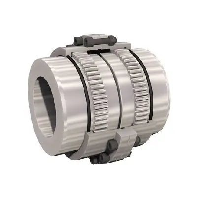
- Flexible Gear Couplings: Flexible gear couplings combine the features of gear couplings and flexible couplings. They consist of two hubs with external gears and a flexible element, such as a membrane or elastomeric material, connecting the hubs. This design allows for some misalignment while providing damping of vibrations and shock absorption.
Each type of gear coupling has its advantages and limitations, and the choice of coupling design depends on the specific requirements of the application, including the level of misalignment, torque capacity, speed, and environmental conditions.
editor by CX 2023-08-17
China Best Sales Industrial Worm Speed Gear Box Reducer Motor With Gearbox WXRV075 Input Shaft top gear
Warranty: 1 year
Applicable Industries: Manufacturing Plant, Machinery Repair Shops, Food & Beverage Factory, Farms, Construction works , Energy & Mining, high precision Gearbox Drive Power Transmission Sell Gearbox Auxiliary Gear Box Cyclo Series Cycloidal gearbox reducer for mixer Other
Customized support: OEM, ODM
Gearing Arrangement: Worm
Output Torque: 2.6-1195N.m
Input Speed: 1400 rpm
Output Speed: 14-280rpm
Product name: Worm Gear Reducer
Color: Blue/Silver or on customer request
Material: Aluminum alloy and casting iron
Application: Machine Tool
Certification: IECEE
Packaging Details: Inner packing: carton; Outer packing: Plywood case
Port: ZheJiang OR HangZhou
| Material Construction | |||
| Worm gear | Inner side: | nodular cast iron QT500 | |
| Outter side: | 9-4 bronze | ||
| Worm shaft | 20 Cr steel with carburizing process to make it harder | ||
| Hardening degree: | surface | HRC56-62 | |
| inner | HB220 to 260 | ||
| Carburizing depth: | 0.3mm to 0.5mm | ||
| Housing | ADC12 aluminium alloy for WXRV30-WXRV090 | ||
| HT200 cast iron for WXRV110-WXRV130 | |||
| Bearing | HCH bearing | ||
| Oil seal | SKF seal for input | ||
| NAK seal for output | |||
| Oil | Synthetic or mineral | ||
Foreign exhibition
Company Information
HangZhou Wanxing reducer Co.,Ltd is established in 1999 and is a professional manufacturer and supplier of NMRV,VF,WP, High quality ammonium phosphate ammonium chloride crusher PLANETARY gearbox/reducer. It is located in HangZhou City of China,with easy access to air port and sea port.
Our company pass the ISO9001:2000 certification. “WANGXING” brand products have been widely used in sectors of enviromental engineering,printing & chemical industry, HW27004500 Series Gas Online Generator logistics.beer ect. In order to improve our products quality,we have established the research and development department with experienced technicians.
Packaging & Shipping Safety Packing Method 1.Inside :Plastic bags with Chemical Desiccant For Gearboxes/Speed Reducer 2.Middle :Individual Carton packaging For Gearboxes/ Speed Reducer 3. Outside :Wooden Box For Gearboxes/ Speed Reducer
FAQ
FAQ:
1. Q: What’s type of your company. A: We are manufacturer.2. Q: what should I provide when I choose gearbox/speed reducer? A: 1) load condition 2) speed of rotation or speed ratio(combination with combine speed reducer can get extra low out putting rotational speed) 3) work circumstance(temperature, humidity,corrosion etc.) 4) space of installation3. Q: How long dose it take to finish my order? A: It depends on your quantity. Generally 25days for 1 20GP, Hollow Structure Helical Gearbox Positioning Rotary Gear box Table Transmission Planetary Speed Reducer 35days for 1 40HQ.4. Q: How can i know the process of my order? A: Detailed picture of the production process will be sent to you to confirm before shipping. Consummation QC system makes it possible to offer you reliable quality
Helical, Straight-Cut, and Spiral-Bevel Gears
If you are planning to use bevel gears in your machine, you need to understand the differences between Helical, Straight-cut, and Spiral bevel gears. This article will introduce you to these gears, as well as their applications. The article will also discuss the benefits and disadvantages of each type of bevel gear. Once you know the differences, you can choose the right gear for your machine. It is easy to learn about spiral bevel gears.
Spiral bevel gear
Spiral bevel gears play a critical role in the aeronautical transmission system. Their failure can cause devastating accidents. Therefore, accurate detection and fault analysis are necessary for maximizing gear system efficiency. This article will discuss the role of computer aided tooth contact analysis in fault detection and meshing pinion position errors. You can use this method to detect problems in spiral bevel gears. Further, you will learn about its application in other transmission systems.
Spiral bevel gears are designed to mesh the gear teeth more slowly and appropriately. Compared to straight bevel gears, spiral bevel gears are less expensive to manufacture with CNC machining. Spiral bevel gears have a wide range of applications and can even be used to reduce the size of drive shafts and bearings. There are many advantages to spiral bevel gears, but most of them are low-cost.
This type of bevel gear has three basic elements: the pinion-gear pair, the load machine, and the output shaft. Each of these is in torsion. Torsional stiffness accounts for the elasticity of the system. Spiral bevel gears are ideal for applications requiring tight backlash monitoring and high-speed operations. CZPT precision machining and adjustable locknuts reduce backlash and allow for precise adjustments. This reduces maintenance and maximizes drive lifespan.
Spiral bevel gears are useful for both high-speed and low-speed applications. High-speed applications require spiral bevel gears for maximum efficiency and speed. They are also ideal for high-speed and high torque, as they can reduce rpm without affecting the vehicle’s speed. They are also great for transferring power between two shafts. Spiral bevel gears are widely used in automotive gears, construction equipment, and a variety of industrial applications.
Hypoid bevel gear
The Hypoid bevel gear is similar to the spiral bevel gear but differs in the shape of the teeth and pinion. The smallest ratio would result in the lowest gear reduction. A Hypoid bevel gear is very durable and efficient. It can be used in confined spaces and weighs less than an equivalent cylindrical gear. It is also a popular choice for high-torque applications. The Hypoid bevel gear is a good choice for applications requiring a high level of speed and torque.
The Hypoid bevel gear has multiple teeth that mesh with each other at the same time. Because of this, the gear transmits torque with very little noise. This allows it to transfer a higher torque with less noise. However, it must be noted that a Hypoid bevel gear is usually more expensive than a spiral bevel gear. The cost of a Hypoid bevel gear is higher, but its benefits make it a popular choice for some applications.
A Hypoid bevel gear can be made of several types. They may differ in the number of teeth and their spiral angles. In general, the smaller hypoid gear has a larger pinion than its counterpart. This means that the hypoid gear is more efficient and stronger than its bevel cousin. It can even be nearly silent if it is well lubricated. Once you’ve made the decision to get a Hypoid bevel gear, be sure to read up on its benefits.
Another common application for a Hypoid bevel gear is in automobiles. These gears are commonly used in the differential in automobiles and trucks. The torque transfer characteristics of the Hypoid gear system make it an excellent choice for many applications. In addition to maximizing efficiency, Hypoid gears also provide smoothness and efficiency. While some people may argue that a spiral bevel gear set is better, this is not an ideal solution for most automobile assemblies.
Helical bevel gear
Compared to helical worm gears, helical bevel gears have a small, compact housing and are structurally optimized. They can be mounted in various ways and feature double chamber shaft seals. In addition, the diameter of the shaft and flange of a helical bevel gear is comparable to that of a worm gear. The gear box of a helical bevel gear unit can be as small as 1.6 inches, or as large as eight cubic feet.
The main characteristic of helical bevel gears is that the teeth on the driver gear are twisted to the left and the helical arc gears have a similar design. In addition to the backlash, the teeth of bevel gears are twisted in a clockwise and counterclockwise direction, depending on the number of helical bevels in the bevel. It is important to note that the tooth contact of a helical bevel gear will be reduced by about ten to twenty percent if there is no offset between the two gears.
In order to create a helical bevel gear, you need to first define the gear and shaft geometry. Once the geometry has been defined, you can proceed to add bosses and perforations. Then, specify the X-Y plane for both the gear and the shaft. Then, the cross section of the gear will be the basis for the solid created after revolution around the X-axis. This way, you can make sure that your gear will be compatible with the pinion.
The development of CNC machines and additive manufacturing processes has greatly simplified the manufacturing process for helical bevel gears. Today, it is possible to design an unlimited number of bevel gear geometry using high-tech machinery. By utilizing the kinematics of a CNC machine center, you can create an unlimited number of gears with the perfect geometry. In the process, you can make both helical bevel gears and spiral bevel gears.
Straight-cut bevel gear
A straight-cut bevel gear is the easiest to manufacture. The first method of manufacturing a straight bevel gear was to use a planer with an indexing head. Later, more efficient methods of manufacturing straight bevel gears were introduced, such as the Revacycle system and the Coniflex system. The latter method is used by CZPT. Here are some of the main benefits of using a straight-cut bevel gear.
A straight-cut bevel gear is defined by its teeth that intersect at the axis of the gear when extended. Straight-cut bevel gears are usually tapered in thickness, with the outer part being larger than the inner portion. Straight-cut bevel gears exhibit instantaneous lines of contact, and are best suited for low-speed, static-load applications. A common application for straight-cut bevel gears is in the differential systems of automobiles.
After being machined, straight-cut bevel gears undergo heat treatment. Case carburizing produces gears with surfaces of 60-63 Rc. Using this method, the pinion is 3 Rc harder than the gear to equalize wear. Flare hardening, flame hardening, and induction hardening methods are rarely used. Finish machining includes turning the outer and inner diameters and special machining processes.
The teeth of a straight-cut bevel gear experience impact and shock loading. Because the teeth of both gears come into contact abruptly, this leads to excessive noise and vibration. The latter limits the speed and power transmission capacity of the gear. On the other hand, a spiral-cut bevel gear experiences gradual but less-destructive loading. It can be used for high-speed applications, but it should be noted that a spiral-cut bevel gear is more complicated to manufacture.
Spur-cut bevel gear
CZPT stocks bevel gears in spiral and straight tooth configurations, in a range of ratios from 1.5 to five. They are also highly remachinable except for the teeth. Spiral bevel gears have a low helix angle and excellent precision properties. CZPT stock bevel gears are manufactured using state-of-the-art technologies and know-how. Compared with spur-cut gears, these have a longer life span.
To determine the strength and durability of a spur-cut bevel gear, you can calculate its MA (mechanical advantage), surface durability (SD), and tooth number (Nb). These values will vary depending on the design and application environment. You can consult the corresponding guides, white papers, and technical specifications to find the best gear for your needs. In addition, CZPT offers a Supplier Discovery Platform that allows you to discover more than 500,000 suppliers.
Another type of spur gear is the double helical gear. It has both left-hand and right-hand helical teeth. This design balances thrust forces and provides extra gear shear area. Helical gears, on the other hand, feature spiral-cut teeth. While both types of gears may generate significant noise and vibration, helical gears are more efficient for high-speed applications. Spur-cut bevel gears may also cause similar effects.
In addition to diametral pitch, the addendum and dedendum have other important properties. The dedendum is the depth of the teeth below the pitch circle. This diameter is the key to determining the center distance between two spur gears. The radius of each pitch circle is equal to the entire depth of the spur gear. Spur gears often use the addendum and dedendum angles to describe the teeth.


China Good quality High quality F series parallel helical gearbox reducer motor top gear
Warranty: 1 year, 1 Year
Applicable Industries: Manufacturing Plant, Machinery Repair Shops, Food & Beverage Factory, Farms
Customized support: OEM, ODM, High power range with big torque use for tranmission line driver R97 coaxial helical gear motor, reducer, gearbox OBM
Gearing Arrangement: Helical
Output Torque: 3.5-36174 N.M
Output Speed: 0.06-180
Product name: High quality F series parallel helical gearbox reducer motor
Efficiency: 94%~98%
Noise Test: 65~70dB
Tooth surface hardness: The hard tooth face
Color: Customized
Certificate: ISO9001:2008
Brand: beiji or custom
Usage: Speed Change
Gears: Helical Gears Transmission Gear Box
Packaging Details: Cartons or wooden cases
Port: HangZhou
High quality F series parallel helical gearbox reducer motor Product Paramenters
| Product Name | High quality F series parallel helical gearbox reducer motor | ||||||
| Type | Parallel shaft geared motor | ||||||
| Model | F37-F177 | ||||||
| Packing | Carton and Wooden Case | ||||||
| Color | Blue/Silver Or On Customer Request | ||||||
| Usages | Industrial Machine: Food Stuff,Ceramics,CHEMICAL,Packing,Dyeing,Woodworking, high precision customized worm reduction gearbox nmrv75 new type worm reducer aluminium motor gear box small reducer Glass. | ||||||
| Brand | beiji or custom | ||||||
Synthesis of Epicyclic Gear Trains for Automotive Automatic Transmissions
In this article, we will discuss the synthesis of epicyclic gear trains for automotive automatic transmissions, their applications, and cost. After you have finished reading, you may want to do some research on the technology yourself. Here are some links to further reading on this topic. They also include an application in hybrid vehicle transmissions. Let’s look at the basic concepts of epicyclic gear trains. They are highly efficient and are a promising alternative to conventional gearing systems.
Synthesis of epicyclic gear trains for automotive automatic transmissions
The main purpose of automotive automatic transmissions is to maintain engine-drive wheel balance. The kinematic structure of epicyclic gear trains (EGTs) is derived from graph representations of these gear trains. The synthesis process is based on an algorithm that generates admissible epicyclic gear trains with up to ten links. This algorithm enables designers to design auto gear trains that have higher performance and better engine-drive wheel balance.
In this paper, we present a MATLAB optimization technique for determining the gear ratios of epicyclic transmission mechanisms. We also enumerate the number of teeth for all gears. Then, we estimate the overall velocity ratios of the obtained EGTs. Then, we analyze the feasibility of the proposed epicyclic gear trains for automotive automatic transmissions by comparing their structural characteristics.
A six-link epicyclic gear train is depicted in the following functional diagram. Each link is represented by a double-bicolor graph. The numbers on the graph represent the corresponding links. Each link has multiple joints. This makes it possible for a user to generate different configurations for each EGT. The numbers on the different graphs have different meanings, and the same applies to the double-bicolor figure.
In the next chapter of this article, we discuss the synthesis of epicyclic gear trains for automotive automatic transaxles. SAE International is an international organization of engineers and technical experts with core competencies in aerospace and automotive. Its charitable arm, the SAE Foundation, supports many programs and initiatives. These include the Collegiate Design Series and A World In Motion(r) and the SAE Foundation’s A World in Motion(r) award.
Applications
The epicyclic gear system is a type of planetary gear train. It can achieve a great speed reduction in a small space. In cars, epicyclic gear trains are often used for the automatic transmission. These gear trains are also useful in hoists and pulley blocks. They have many applications in both mechanical and electrical engineering. They can be used for high-speed transmission and require less space than other types of gear trains.
The advantages of an epicyclic gear train include its compact structure, low weight, and high power density. However, they are not without disadvantages. Gear losses in epicyclic gear trains are a result of friction between gear tooth surfaces, churning of lubricating oil, and the friction between shaft support bearings and sprockets. This loss of power is called latent power, and previous research has demonstrated that this loss is tremendous.
The epicyclic gear train is commonly used for high-speed transmissions, but it also has a small footprint and is suitable for a variety of applications. It is used as differential gears in speed frames, to drive bobbins, and for the Roper positive let-off in looms. In addition, it is easy to fabricate, making it an excellent choice for a variety of industrial settings.
Another example of an epicyclic gear train is the planetary gear train. It consists of two gears with a ring in the middle and the sun gear in the outer ring. Each gear is mounted so that its center rotates around the ring of the other gear. The planet gear and sun gear are designed so that their pitch circles do not slip and are in sync. The planet gear has a point on the pitch circle that traces the epicycloid curve.
This gear system also offers a lower MTTR than other types of planetary gears. The main disadvantage of these gear sets is the large number of bearings they need to run. Moreover, planetary gears are more maintenance-intensive than parallel shaft gears. This makes them more difficult to monitor and repair. The MTTR is also lower compared to parallel shaft gears. They can also be a little off on their axis, causing them to misalign or lose their efficiency.
Another example of an epicyclic gear train is the differential gear box of an automobile. These gears are used in wrist watches, lathe machines, and automotives to transmit power. In addition, they are used in many other applications, including in aircrafts. They are quiet and durable, making them an excellent choice for many applications. They are used in transmission, textile machines, and even aerospace. A pitch point is the path between two teeth in a gear set. The axial pitch of one gear can be increased by increasing its base circle.
An epicyclic gear is also known as an involute gear. The number of teeth in each gear determines its rate of rotation. A 24-tooth sun gear produces an N-tooth planet gear with a ratio of 3/2. A 24-tooth sun gear equals a -3/2 planet gear ratio. Consequently, the epicyclic gear system provides high torque for driving wheels. However, this gear train is not widely used in vehicles.
Cost
The cost of epicyclic gearing is lower when they are tooled rather than manufactured on a normal N/C milling machine. The epicyclic carriers should be manufactured in a casting and tooled using a single-purpose machine that has multiple cutters to cut the material simultaneously. This approach is widely used for industrial applications and is particularly useful in the automotive sector. The benefits of a well-made epicyclic gear transmission are numerous.
An example of this is the planetary arrangement where the planets orbit the sun while rotating on its shaft. The resulting speed of each gear depends on the number of teeth and the speed of the carrier. Epicyclic gears can be tricky to calculate relative speeds, as they must figure out the relative speed of the sun and the planet. The fixed sun is not at zero RPM at mesh, so the relative speed must be calculated.
In order to determine the mesh power transmission, epicyclic gears must be designed to be able to “float.” If the tangential load is too low, there will be less load sharing. An epicyclic gear must be able to allow “float.” It should also allow for some tangential load and pitch-line velocities. The higher these factors, the more efficient the gear set will be.
An epicyclic gear train consists of two or more spur gears placed circumferentially. These gears are arranged so that the planet gear rolls inside the pitch circle of the fixed outer gear ring. This curve is called a hypocycloid. An epicyclic gear train with a planet engaging a sun gear is called a planetary gear train. The sun gear is fixed, while the planet gear is driven.
An epicyclic gear train contains several meshes. Each gear has a different number of meshes, which translates into RPM. The epicyclic gear can increase the load application frequency by translating input torque into the meshes. The epicyclic gear train consists of 3 gears, the sun, planet, and ring. The sun gear is the center gear, while the planets orbit the sun. The ring gear has several teeth, which increases the gear speed.
Another type of epicyclic gear is the planetary gearbox. This gear box has multiple toothed wheels rotating around a central shaft. Its low-profile design makes it a popular choice for space-constrained applications. This gearbox type is used in automatic transmissions. In addition, it is used for many industrial uses involving electric gear motors. The type of gearbox you use will depend on the speed and torque of the input and output shafts.
in Edmonton Canada sales price shop near me near me shop factory supplier 12V 24V 36V 48V DC Brushed Worm Gear Motor with Factory Price manufacturer best Cost Custom Cheap wholesaler

Far more importantly, we make special elements in accordance to supplied drawings/samples and warmly welcome OEM inquiries. we offer you one-cease solution for the obtain of mechanical electrical power transmission products in China. We have exported our products to Korea, Turkey, Bulgaria, Romania, Russia, Italy, Norway, the Usa, Canada, etc. 12V 24V 36V 48V DC Brushed Worm EPT EPT with Manufacturing unit Cost
PG36M555 Series
voltage: 3VDC 6VDC 9VDC 12VDC 24VDC
Speed selection: 3000-9500rpm
EPTT: three.3-13w
Typical purposes: EPT air-conditioning valve, Amusement equipment, Coin
Refund products, Grill, Oven, Peristaltic pumps, ATM bank
EPTT system, Robot, Medical gear, Place of work
EPT, EPTT EPTs, EPTT actuator.
Excess weight: 320~400g/PCS(approx)
EPTT details: CTN dimensions: 32X28XH26cm 40PCS/CTN G. W. 16Kgs
|
|||||||||||||||||||||||||||||||||||||||||||||||||||||||||||||||||||||||||||||||||||||||||||||||||||
|
|||||||||||||||||||||||||||||||||||||||||||||||||||||||||||||||||||||||||||||||||||||||||||||||||||
|
|||||||||||||||||||||||||||||||||||||||||||||||||||||||||||||||||||||||||||||||||||||||||||||||||||
EPTT Introduction


in Budapest Hungary sales price shop near me near me shop factory supplier Hot Sale Electrical Speed Gear Motor with Long Life manufacturer best Cost Custom Cheap wholesaler

Every method, every segment, every single operate in EPG is demanded to be completed one particular stage subsequent an additional, carefully and cautiously, from content selection, reformation to production add-ons, from elements warmth treatment method to computerized assembly, from good quality control to merchandise inspection and screening and from order working to right after income service. EPG will constantly adhere to it organization spirit of being functional, progressive, effective and excellent to make the best international transmission drive. With EPG manufacturer registered in a lot more than 70 countries like The usa , Europe , Japan and so on, it has associates among planet top enterprises, such as JOHNDEERE, NEW HOLLAND, CLAAS, HONDA, KUBOTA, YANMAR, etc. Scorching Sale EPT Velocity EPT EPT with EPTT EPT
Primary voltage,6VDC,12VDC,24VDC,36VDC
Standard programs, Auto shutter,Income detector,Binding EPTT,EPTT Tv set
rack,EPTT financial institution note EPTT,Limelight,Tissue EPTT,Office
gear,EPTT EPTs,EPTT actuator.
Excess weight,four hundred~450g/pcs(approx)
EPTT information,CTN size:35 times26 timesH19cm 10pcs/CTN G.W.12kgs
EPTT Introduction