Tag Archives: machine shaft

China Universal Joints Shaft Coupling Motor Disc Coupler Machine Shaft Coupler Steering Connector coupling and types of coupling

Merchandise Description

Specification OF Common Joint —Speedway:


Item Description

 Drive Shaft  Description:
 

Merchandise Universal Joints Shaft Coupling Motor Disc Coupler Machine Shaft Coupler Steering Connector 
OEM Common Joints Shaft Coupling
Content 20Cr or 20CrMnTi
Use Following industry
MOQ fifty cps

 
We offer propeller shaft OEM service and we can also produce propeller shaft according to your samples and drawings.
 
 
Package and Supply:
 
Neutral Packing Or Customerized Packing.
 
We settle for customerized model packing if the quantity is great. 
 
Neutral Packing implies each propeller shaft is packed with foam polybags, then it will be set into box, and all propeller shafts are packed in cartons lastly.
 
All of the products are properly packed.
 
Supply time is 35-forty five days as regular.
Packing display


Organization Profile

Certifications


FAQ

After-sales Service: 1 Year
Warranty: 1 Year
Condition: New
Color: Silver
Structure: Double
Material: 20cr or 20crmnti

###

Samples:
US$ 300/Piece
1 Piece(Min.Order)

|
Request Sample

###

Item Universal Joints Shaft Coupling Motor Disc Coupler Machine Shaft Coupler Steering Connector 
OEM Universal Joints Shaft Coupling
Material 20Cr or 20CrMnTi
Use After market
MOQ 50 cps

Understanding the Different Types of Couplings

A coupling is a device that joins two rotating shafts together. It transmits power from one to the other and is designed to allow some amount of end-movement and misalignment. It is a simple mechanism that is extremely common in many industries. Learn more about couplings in this article.

Flexible coupling

When choosing the correct flexible coupling for your application, there are several factors to consider. One of the most important factors is backlash, which is the amount of rotational play introduced by moving parts. Other factors to consider include lubrication and accessibility for maintenance. Choosing the right flexible coupling can be challenging, but it is possible to find the right fit for your specific application.
A flexible coupling is an excellent choice for applications that require high alignment accuracy, which is essential for reliable system performance. These couplings can compensate for angular and parallel misalignment, ensuring proper positioning between the driving and driven shafts. In addition, flexible couplings are more affordable than most traditional couplings.
The most common flexible coupling is the elastomeric type, which uses a resilient material to transmit torque. These couplings can be made of plastic or rubber. In either case, they can be relatively lightweight compared to other types of couplings. Elastomeric couplings can also be used for high-speed applications.
Another important factor to consider when selecting the best Flexible Coupling is the pipe you’re connecting. Some couplings are easier to install than others, and some even have tapered edges to make them slide easily on the pipe. Regardless of the choice you make, it’s crucial to remember that proper installation is critical for reliability and safety.
gearbox

CZPT coupling

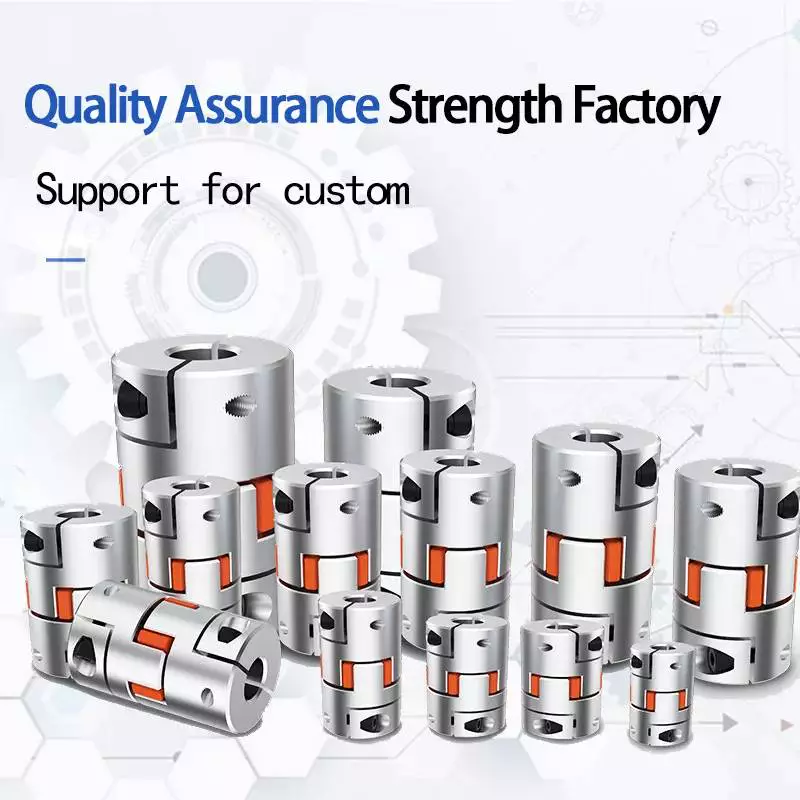
An CZPT coupling is a flexible, mechanical coupling that features a high degree of angular misalignment and eccentricity. They are available in different lengths, with MOL being the longest. They are ideal for applications that involve high parallel misalignment, limited assembly access, electrical insulation, and other conditions.
CZPT couplings are a versatile type of coupling, and they are often used to connect parallel shafts. They work by transmitting torque from one to the other using the same speed and rotation mechanism. They are available in various materials, including aluminum, brass, and polymers. In addition, they can work under high temperatures.
One of the main benefits of using an CZPT coupling is the fact that it does not require the use of a gearbox. These couplings are flexible, and their design allows them to cope with misalignment problems that may occur in power transmission applications. They are also able to absorb shock.
Another advantage of CZPT couplings is that they are suitable for systems with low-to-medium amounts of shaft misalignment. Because their friction is limited to the surface of the hubs, they are able to accommodate low bearing loads. CZPT couplings can also be used in systems with limited shaft access, since the disks are easily removed.

Clamped coupling

Clamped couplings are designed to provide a high-strength connection between two objects. A standard coupling has two parts: a nipple and a clamp sleeve. Each part is designed in such a way as to cooperate with each other. The sleeve and clamp are made of rubber. A reinforcing braid is often used to protect the exposed steel braid from rusting.
PIC Design provides a wide variety of standard clamping couplings for many different industries. These include medical, dental, military, laboratory, and precision industrial control equipment. They have a simple design that makes them ideal for these applications. Clamped couplings are also available for custom manufacturing. These couplings are available in metric, inch, and Metric.
The most common type of clamp coupling is a hose clamp. This type of coupling is used to connect two hoses or piping units. It consists of two conical binding sleeves that fit into the ends of the two parts. The coupling is then tightened with a screwdriver. It’s a versatile coupling because it allows two piping units or hoses to be joined together.
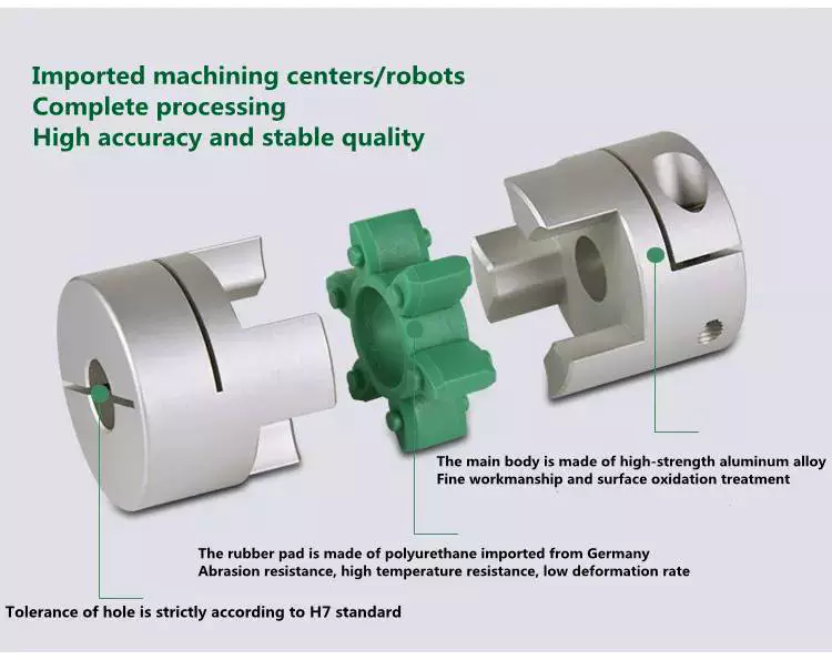
Another type of clamp coupling is the two-piece clamp coupling. The two-piece design allows for a quick and easy installation. Unlike other types of couplings, the clamp coupling is not necessary to remove the bearings before installing it. Its keyway is designed with shims in place so that it fits over the shaft. These couplings are available in different sizes, and they are made of steel or dutile iron.
gearbox

Helicoidal coupling

Helicoidal coupling is a form of nonlinear coupling between two molecules. It occurs when the molecules in a double helix are subjected to oscillations. These oscillations can occur either in the right or left-handed direction. These oscillations are called solitons. Helicoidal coupling can provide quantitative or qualitative support to a structure, such as an electron.

Split Muff coupling

The Split-Muff Coupling market report provides detailed market analysis and key insights. The study covers the market size, segmentation, growth and sales forecast. It also examines key factors driving the market growth and limiting its development. The report also covers current trends and vendor landscapes. Therefore, you can get a deep understanding of the Split-Muff Coupling industry and make the right business decisions.
The report also provides data on the competitive landscape and the latest product and technology innovations. It also provides information on market size, production and income. It also covers the impact of the COVID-19 regulations. The market report is a valuable resource for companies looking to expand their businesses, or to improve existing ones.
In terms of application, Split-Muff Couplings can be used in light to medium duty applications. They are shaped like a semi-cylindrical disc that fits over a shaft. Both parts are threaded for assembly and disassembly. It can be disassembled easily and quickly, and can be used for medium to heavy-duty applications with moderate speeds.
Split Muff couplings are the most popular type of couplings for transferring wet and abrasive materials. Their flanged end fits on most major brands of smooth material muff hoses. In addition, this type of coupling is corrosion-resistant and easy to install. It also does not require any adjustments to the drive shaft’s position.
gearbox

Flexible beam coupling

The Flexible beam coupling is one of the most popular types of couplings in the industry. It is comprised of two sets of parallel coils separated by a solid member, and it offers a wide range of torsional stiffness. These couplings are made of aluminum alloy or stainless steel. They offer excellent flexibility and are less expensive than many other types of couplings. They also require zero maintenance and can tolerate shaft misalignment.
Beam couplings are categorized into two types: helical and axial. The former is characterized by a high degree of flexibility, while the latter is used to compensate for higher misalignment. Both types are suitable for small torque applications and are available in a wide range of shaft sizes.
Flexible beam couplings are available in metric and US sizes, and feature a variety of options. They feature stainless steel or aluminum materials and are highly durable and corrosion-resistant. They also offer high torque capacities and excellent fatigue resistance. Flexible beam couplings are available with a wide range of options to meet your unique application needs.
China Universal Joints Shaft Coupling Motor Disc Coupler Machine Shaft Coupler Steering Connector     coupling and types of couplingChina Universal Joints Shaft Coupling Motor Disc Coupler Machine Shaft Coupler Steering Connector     coupling and types of coupling
editor by czh 2023-01-24

China factory Cutting Bits Mercedes Drive Shaft Gears in Car CZPT Machine near me shop

Product Description


Car Gears 8.25KW Standard CZPT Machine

The car gears CZPT machine adopts the principle of high-pressure water CZPT system, and the water pressure can reach 1.8-2.0mpa. It can effectively remove the scale of auto gear forgings under high temperature, and the cooling range of forgings can be controlled within 30 ºC. At present, this CZPT equipment has been widely used in China, and the improvement of forging surface quality has been recognized by the market.


The CZPT machine from CZPT technology, the main body of the equipment is composed of a pressure system, a transmission system and a filtration system. The 3 systems jointly use the principle of high-pressure water CZPT to complete the cleaning process of the forging scale.

The high-pressure water CZPT system is adopted, and the high-pressure water generated by the high-pressure water pump enters the CZPT nozzle and is sprayed on the surface of the forging (or intermediate billet). The oxide scale has undergone the process of being cut, rapidly cooled and contracted, peeled from the base material, and washed away from the surface of the forging, thereby removing the oxide scale.

The CZPT machine is equipped with 2 water tanks. The water tank has a built-in filter screen and a net basket to form the filter system of the equipment to prevent oxide scale from entering the water pump and affect the service life of the equipment. At the same time, it is equipped with a magnetic shovel to clean the oxide scale in the water tank.

The frequency conversion motor and the chain constitute the transmission system, which is responsible for transporting the forgings for the cleaning process. The transmission speed of the chain can be adjusted to ensure that the temperature of the forgings after cleaning is small, which is conducive to subsequent forging.

1,The main body of the water tank is made of 304 stainless steel and painted with blue sky

2,The exit and entrance adopt integral welding with high parallelism

3,Front and back built-in baffle, less splash, easy maintenance

4,Integral cover to protect pump motor

5,Compared with the conventional CZPT machine, the flow rate is large, and it is suitable for the refractory oxide scale products6,The nozzle mounting seat is welded with stainless steel, which is easy to maintain

7,Comprehensive treatment of oxide skin, less lower the temperature

8,After removing the oxide scale, the metallographic structure of the product has no chang


1. What kind of forging pieces is CZPT machine suitable for?

The CZPT machine is applicable to the forging production line. It can clean the oxide scale generated after heating by induction CZPT and effectively improve the surface quality of products.
 

2. How to choose the model of CZPT machine? Can it be customized?

You can select the corresponding standard model through the diameter of the round bar and the size of the billet after making. For details, please check the parameter navigation bar of the webpage. If there is a need for customization, we can also provide customized services according to the customer’s raw material size and process.
 

3. How to daily maintain CZPT equipment?

We will recommend that customers regularly clean the oxide scale in the water tank. You only need to use a magnetic shovel to remove most of the oxide scale. But also regularly replace the water in the water tank to ensure a normal filtration cycle.
 

4. Does the principle of high-pressure water CZPT change the metallographic structure?

This method has been tested by a third-party organization. The test report shows that there is no change in the metallographic structure before and after cleaning, which has no effect on the later process.
 

5. How effective is the CZPT machine? Is there a reference video for CZPT equipment?

Descaling Technology has served more than a thousand forging factories in China, and received a large number of market feedback results. Regarding the on-site use of the equipment, please click into official YouTube account as below for more information.

Name Model Dimension(mm) Equipment power Pump brand Flow
Small standard descaling machine DMS-80-20 1300*1500*1460 8.25KW Nanfang pump 8m³/h
Suitable for bar diameter(mm) Width and height after blank making(mm) Number of nozzles Material Transmission motor Chain specification
15-80 110*80 18 304 stainless steel Speed control motor 16A

How to Design a Forging Spur Gear

Before you start designing your own spur gear, you need to understand its main components. Among them are Forging, Keyway, Spline, Set screw and other types. Understanding the differences between these types of spur gears is essential for making an informed decision. To learn more, keep reading. Also, don’t hesitate to contact me for assistance! Listed below are some helpful tips and tricks to design a spur gear. Hopefully, they will help you design the spur gear of your dreams.
Gear

Forging spur gears

Forging spur gears is one of the most important processes of automotive transmission components. The manufacturing process is complex and involves several steps, such as blank spheroidizing, hot forging, annealing, phosphating, and saponification. The material used for spur gears is typically 20CrMnTi. The process is completed by applying a continuous through extrusion forming method with dies designed for the sizing band length L and Splitting angle thickness T.
The process of forging spur gears can also use polyacetal (POM), a strong plastic commonly used for the manufacture of gears. This material is easy to mold and shape, and after hardening, it is extremely stiff and abrasion resistant. A number of metals and alloys are used for spur gears, including forged steel, stainless steel, and aluminum. Listed below are the different types of materials used in gear manufacturing and their advantages and disadvantages.
A spur gear’s tooth size is measured in modules, or m. Each number represents the number of teeth in the gear. As the number of teeth increases, so does its size. In general, the higher the number of teeth, the larger the module is. A high module gear has a large pressure angle. It’s also important to remember that spur gears must have the same module as the gears they are used to drive.

Set screw spur gears

A modern industry cannot function without set screw spur gears. These gears are highly efficient and are widely used in a variety of applications. Their design involves the calculation of speed and torque, which are both critical factors. The MEP model, for instance, considers the changing rigidity of a tooth pair along its path. The results are used to determine the type of spur gear required. Listed below are some tips for choosing a spur gear:
Type A. This type of gear does not have a hub. The gear itself is flat with a small hole in the middle. Set screw gears are most commonly used for lightweight applications without loads. The metal thickness can range from 0.25 mm to 3 mm. Set screw gears are also used for large machines that need to be strong and durable. This article provides an introduction to the different types of spur gears and how they differ from one another.
Pin Hub. Pin hub spur gears use a set screw to secure the pin. These gears are often connected to a shaft by dowel, spring, or roll pins. The pin is drilled to the precise diameter to fit inside the gear, so that it does not come loose. Pin hub spur gears have high tolerances, as the hole is not large enough to completely grip the shaft. This type of gear is generally the most expensive of the three.
Gear

Keyway spur gears

In today’s modern industry, spur gear transmissions are widely used to transfer power. These types of transmissions provide excellent efficiency but can be susceptible to power losses. These losses must be estimated during the design process. A key component of this analysis is the calculation of the contact area (2b) of the gear pair. However, this value is not necessarily applicable to every spur gear. Here are some examples of how to calculate this area. (See Figure 2)
Spur gears are characterized by having teeth parallel to the shafts and axis, and a pitch line velocity of up to 25 m/s is considered high. In addition, they are more efficient than helical gears of the same size. Unlike helical gears, spur gears are generally considered positive gears. They are often used for applications in which noise control is not an issue. The symmetry of the spur gear makes them especially suitable for applications where a constant speed is required.
Besides using a helical spur gear for the transmission, the gear can also have a standard tooth shape. Unlike helical gears, spur gears with an involute tooth form have thick roots, which prevents wear from the teeth. These gears are easily made with conventional production tools. The involute shape is an ideal choice for small-scale production and is one of the most popular types of spur gears.

Spline spur gears

When considering the types of spur gears that are used, it’s important to note the differences between the two. A spur gear, also called an involute gear, generates torque and regulates speed. It’s most common in car engines, but is also used in everyday appliances. However, one of the most significant drawbacks of spur gears is their noise. Because spur gears mesh only one tooth at a time, they create a high amount of stress and noise, making them unsuitable for everyday use.
The contact stress distribution chart represents the flank area of each gear tooth and the distance in both the axial and profile direction. A high contact area is located toward the center of the gear, which is caused by the micro-geometry of the gear. A positive l value indicates that there is no misalignment of the spline teeth on the interface with the helix hand. The opposite is true for negative l values.
Using an upper bound technique, Abdul and Dean studied the forging of spur gear forms. They assumed that the tooth profile would be a straight line. They also examined the non-dimensional forging pressure of a spline. Spline spur gears are commonly used in motors, gearboxes, and drills. The strength of spur gears and splines is primarily dependent on their radii and tooth diameter.
SUS303 and SUS304 stainless steel spur gears

Stainless steel spur gears are manufactured using different techniques, which depend on the material and the application. The most common process used in manufacturing them is cutting. Other processes involve rolling, casting, and forging. In addition, plastic spur gears are produced by injection molding, depending on the quantity of production required. SUS303 and SUS304 stainless steel spur gears can be made using a variety of materials, including structural carbon steel S45C, gray cast iron FC200, nonferrous metal C3604, engineering plastic MC901, and stainless steel.
The differences between 304 and 303 stainless steel spur gears lie in their composition. The two types of stainless steel share a common design, but have varying chemical compositions. China and Japan use the letters SUS304 and SUS303, which refer to their varying degrees of composition. As with most types of stainless steel, the two different grades are made to be used in industrial applications, such as planetary gears and spur gears.
Gear

Stainless steel spur gears

There are several things to look for in a stainless steel spur gear, including the diametral pitch, the number of teeth per unit diameter, and the angular velocity of the teeth. All of these aspects are critical to the performance of a spur gear, and the proper dimensional measurements are essential to the design and functionality of a spur gear. Those in the industry should be familiar with the terms used to describe spur gear parts, both to ensure clarity in production and in purchase orders.
A spur gear is a type of precision cylindrical gear with parallel teeth arranged in a rim. It is used in various applications, such as outboard motors, winches, construction equipment, lawn and garden equipment, turbine drives, pumps, centrifuges, and a variety of other machines. A spur gear is typically made from stainless steel and has a high level of durability. It is the most commonly used type of gear.
Stainless steel spur gears can come in many different shapes and sizes. Stainless steel spur gears are generally made of SUS304 or SUS303 stainless steel, which are used for their higher machinability. These gears are then heat-treated with nitriding or tooth surface induction. Unlike conventional gears, which need tooth grinding after heat-treating, stainless steel spur gears have a low wear rate and high machinability.