Motor coupling reducer couples necklace pair bathing suit bracelet stainless magnetic conduit hydraulic matching outfit gear coupling quick release flexible
Application of Reducer Coupling
A reducer coupling is a pipe fitting that is used to connect 2 pipes of different sizes. It is a type of adapter that allows for a smooth transition between the 2 pipes. Reducer couplings are available in a variety of sizes and materials, and they can be used in a variety of applications.
Some of the most common applications for reducer couplings include:
Connecting pipes of different sizes: Reducer couplings are used to connect pipes of different sizes, such as when you need to connect a smaller pipe to a larger pipe. This is a common application in plumbing, HVAC, and other types of construction.
Changing the direction of a pipe: Reducer couplings can also be used to change the direction of a pipe. This is a common application in plumbing, as it allows you to route pipes in a way that is both efficient and aesthetically pleasing.
Repairing a damaged pipe: Reducer couplings can also be used to repair a damaged pipe. This is a common application in plumbing, as it allows you to repair a pipe without having to replace the entire pipe.
Reducer couplings are a versatile and useful tool that can be used in a variety of applications. They are an easy and affordable way to connect pipes of different sizes, change the direction of a pipe, or repair a damaged pipe.
Here are some additional tips for using reducer couplings:
Make sure that the reducer coupling is the correct size for the pipes that you are connecting.
Use a pipe joint compound to seal the reducer coupling.
Tighten the reducer couplings by hand, and then use a wrench to tighten them further.
Do not overtighten the reducer couplings, as this can damage the pipes.
By following these tips, you can safely and effectively use reducer couplings to connect pipes of different sizes.
What Industries Commonly Use Gear Couplings for Power Transmission?
Gear couplings are widely used in various industries for power transmission due to their ability to transmit high torque loads and accommodate misalignments. Some of the industries that commonly utilize gear couplings include:
Steel Industry: Gear couplings are extensively used in the steel industry for connecting heavy-duty equipment like rolling mills, continuous casting machines, and other steel processing machinery.
Mining and Quarrying: In mining and quarrying applications, gear couplings are employed to transmit power in conveyor systems, crushers, and heavy excavating machinery.
Pulp and Paper: The pulp and paper industry uses gear couplings in machines like paper mills, pulp refiners, and stock preparation equipment.
Marine: Gear couplings are utilized in marine propulsion systems, providing a reliable connection between the engine and the propeller shafts.
Oil and Gas: Gear couplings find use in the oil and gas industry for connecting pumps, compressors, and other equipment used in upstream and downstream operations.
Power Generation: Gear couplings are employed in power plants to connect generators, turbines, and other rotating equipment.
Automotive: Gear couplings are used in automotive applications, particularly in heavy-duty vehicles and machinery like off-road vehicles, construction equipment, and agricultural machinery.
Chemical and Petrochemical: In chemical processing plants, gear couplings are employed in agitators, mixers, and various equipment where power transmission is crucial.
Cement and Aggregate: Gear couplings are used in cement plants and aggregate processing equipment for power transmission in crushers, kilns, and conveyors.
These are just a few examples, and gear couplings can be found in various other industries where reliable power transmission is essential. Their robust design and ability to withstand harsh operating conditions make them a popular choice for heavy-duty applications across different sectors.
1-0-0. p. 211. Retrieved 17 May 2-0-0. p. 86. Retrieved 30 January 2015. Green 1996, pp. 2337-2361 “ANSI G7 Standard Roller Chain – Tsubaki Europe”. Tsubaki Europe. Tsubakimoto Europe B.V. Retrieved 18 June 2. External links Wikimedia Commons has media related to Roller chains. The Complete Xihu (West Lake) Dis. to Chain Categories: Chain drivesMechanical power transmissionMechanical power control
Why Choose Us 1. Reliable Quality Assurance System 2. Cutting-Edge Computer-Controlled CNC Machines 3. Bespoke Solutions from Highly Experienced Specialists 4. Customization and OEM Available for Specific Application 5. Extensive Inventory of Spare Parts and Accessories 6. Well-Developed CZPT Marketing Network 7. Efficient After-Sale Service System
Materials Used in Manufacturing Gear Couplings
Gear couplings are designed to transmit torque between shafts while accommodating misalignment. To ensure the durability and reliability of gear couplings, manufacturers use a variety of materials, each with its specific properties. Commonly used materials in manufacturing gear couplings include:
Steel: Steel is the most widely used material for gear couplings. It offers excellent strength, durability, and resistance to wear and fatigue. Steel gear couplings are suitable for a wide range of applications, including heavy-duty industrial machinery.
Stainless Steel: Stainless steel is chosen for gear couplings that require resistance to corrosion and high-temperature environments. Stainless steel couplings are commonly used in food processing, pharmaceutical, and chemical industries.
Alloy Steel: Alloy steel is utilized to enhance specific properties, such as increased strength and improved performance under high loads and extreme conditions. Alloy steel gear couplings are ideal for demanding applications in heavy industries.
Cast Iron: Cast iron is known for its excellent machinability and good resistance to wear. Cast iron gear couplings are suitable for low to moderate torque applications and can be cost-effective in certain scenarios.
Non-Metallic Materials: In some cases, non-metallic materials like nylon or urethane may be used for specific gear coupling applications, especially in situations where electrical isolation or chemical resistance is required.
The choice of material depends on the application’s demands, including the torque, speed, environmental conditions, and budget considerations. Gear coupling manufacturers carefully select materials that will provide optimal performance and longevity while meeting the specific requirements of the intended application.
A fluid coupling is a torque converter used in mechanical power transmission systems to transmit torque from 1 rotating shaft to another. It consists of 2 halves, the impeller, and the runner, which are placed in a housing filled with a hydraulic fluid such as oil or water.
When one-half of the fluid coupling is rotated, it creates a fluid flow within the housing, which in turn causes the other half to rotate. The fluid coupling uses fluid dynamics principles to transmit torque between the 2 halves, with the amount of torque being proportional to the speed difference between the 2 shafts.
One of the key advantages of a fluid coupling is its ability to provide a smooth and gradual torque transfer between the 2 shafts, without any mechanical connection. This can help to reduce wear and tear on the equipment and improve overall system efficiency.
Fluid couplings are commonly used in various industrial applications, including mining, construction, and marine equipment. They are also used in automotive transmissions, where they can help provide a smooth and efficient torque transfer between the engine and the wheels.
Overall, a fluid coupling provides a reliable and efficient way to transmit torque between 2 rotating shafts, without any mechanical connection. With their ability to provide a smooth and gradual torque transfer, they are a popular choice for a wide range of industrial and automotive applications.
Selection of Gear Couplings for Specific Applications
Choosing the appropriate gear coupling for a specific application involves considering several factors to ensure optimal performance and reliability. Here are the key steps in the selection process:
Identify Application Requirements: Understand the specific requirements of the application, including the torque and speed requirements, operating conditions, and the amount of angular and axial misalignment expected in the system.
Calculate Torque and Speed: Determine the required torque and speed ratings for the gear coupling based on the power transmission needs of the application. Consider both peak and continuous torque requirements.
Consider Misalignment: Evaluate the amount and type of misalignment that the gear coupling needs to accommodate. Different gear coupling designs have varying degrees of misalignment capabilities, so it’s essential to choose one that can handle the expected misalignment in the system.
Check Space Constraints: Consider the available space for installing the gear coupling. Some applications may have limited space, requiring compact or specially designed couplings to fit properly.
Assess Environmental Conditions: Determine if the application involves exposure to extreme temperatures, corrosive substances, or other harsh environmental factors. Select a gear coupling made from materials that can withstand the specific environmental conditions.
Consider Maintenance Requirements: Evaluate the maintenance needs of the gear coupling. Some designs may require more frequent maintenance than others. For applications where regular maintenance is challenging, consider maintenance-free gear coupling options.
Check Industry Standards and Certifications: Ensure that the selected gear coupling meets relevant industry standards and certifications to guarantee quality and safety.
Consult with Experts: If needed, seek guidance from coupling manufacturers or engineering experts who can provide valuable insights and recommendations based on their experience and expertise.
By carefully considering these factors and understanding the specific demands of the application, you can select the most suitable gear coupling that will provide reliable and efficient power transmission while minimizing the risk of premature failure or downtime.
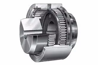
The Chain coupling is composed of a duplex roller chain and a pair of coupling sprockets. The function of connection and detachment is done by the joint of chain. It has the characteristic of compact and powerful, excellent durability, safe and smart, simple installation and easy alignment. The Xihu (West Lake) Dis.hua Chain coupling is suitable for a wide range of coupling applications.
Roller chain( Coupling Chains)
Though Hans Renold is credited with inventing the roller chain in 1880, sketches by Leonardo da Vinci in the 16th century show a chain with a roller bearing.Coupling chains)Coupling chains
Roller chain or bush roller chain is the type of chain drive most commonly used for transmission of mechanical power on many kinds of domestic, industrial and agricultural machinery, including conveyors, wire- and tube-drawing machines, printing presses, cars, motorcycles, and bicycles. It consists of a series of short cylindrical rollers held together by side links. It is driven by a toothed wheel called a sprocket. It is a simple, reliable, and efficient[1] means of power transmission.
Chain No.
Pitch
P
mm
Roller diameter
d1max mm
Width between inner plates b1min mm
Pin diameter
d2max mm
Pin length
Inner plate depth h2max mm
Plate thickness
Tmax mm
Transverse pitch Pt mm
Tensile strength
Qmin kN/lbf
Average tensile strength Q0 kN
Weight per piece q kg/pc
Lmax mm
Lcmax mm
4012
12.7-0-0. p. 211. Retrieved 17 May 2-0-0. p. 86. Retrieved 30 January 2015. Green 1996, pp. 2337-2361 “ANSI G7 Standard Roller Chain – Tsubaki Europe”. Tsubaki Europe. Tsubakimoto Europe B.V. Retrieved 18 June 2. External links Wikimedia Commons has media related to Roller chains. The Complete Xihu (West Lake) Dis. to Chain Categories: Chain drivesMechanical power transmissionMechanical power control
Why Choose Us 1. Reliable Quality Assurance System 2. Cutting-Edge Computer-Controlled CNC Machines 3. Bespoke Solutions from Highly Experienced Specialists 4. Customization and OEM Available for Specific Application 5. Extensive Inventory of Spare Parts and Accessories 6. Well-Developed CZPT Marketing Network 7. Efficient After-Sale Service System
Types of Gear Coupling Designs
There are several types of gear coupling designs available, each with its own specific characteristics and applications. The main types of gear couplings are:
Sleeve Gear Couplings: Sleeve gear couplings consist of two hubs with external gears and a center sleeve with internal gears. The hubs are mounted on the shaft ends, and the center sleeve connects the two hubs. This design allows for angular and axial misalignment while transmitting torque between the shafts. Sleeve gear couplings are suitable for general-purpose applications and offer easy maintenance.
Continuous Sleeve Gear Couplings: Continuous sleeve gear couplings are an improved version of sleeve gear couplings. In this design, the center sleeve is extended to cover the entire length of the hubs, providing additional support and increasing torque capacity. The continuous sleeve design reduces the bending effect on the shafts and allows for higher torque transmission.
Flanged Sleeve Gear Couplings: Flanged sleeve gear couplings are similar to continuous sleeve couplings but include flanges at the ends of the center sleeve. These flanges provide extra support and help maintain proper alignment between the shafts. Flanged sleeve gear couplings are commonly used in high-speed and heavy-duty applications.
Half Gear Couplings: Half gear couplings, also known as semi-rigid gear couplings, consist of one flexible half and one rigid half. The flexible half has internal gear teeth, while the rigid half has external gear teeth. This design allows for angular misalignment while offering higher torque capacity than fully flexible couplings. Half gear couplings are often used in applications where some degree of misalignment is expected, but not as much as what sleeve gear couplings can handle.
Full Gear Couplings: Full gear couplings consist of two hubs with external gear teeth that mesh directly with each other. This design provides high torque capacity and is suitable for applications requiring minimal misalignment. Full gear couplings offer excellent torsional rigidity and are often used in precision applications where accurate shaft alignment is critical.
Flexible Gear Couplings: Flexible gear couplings combine the features of gear couplings and flexible couplings. They consist of two hubs with external gears and a flexible element, such as a membrane or elastomeric material, connecting the hubs. This design allows for some misalignment while providing damping of vibrations and shock absorption.
Each type of gear coupling has its advantages and limitations, and the choice of coupling design depends on the specific requirements of the application, including the level of misalignment, torque capacity, speed, and environmental conditions.
A coupling is a device that connects two shafts and transmits power from one to the other. Its main purpose is to join two pieces of rotating equipment. It also allows for some degree of misalignment or end movement. Here are a few examples of coupling types: Beam coupling, Flexible coupling, Magnetic coupling, and Shaft coupling.
Beam coupling
Beam couplings are used to couple motors and other devices. They are available in several types, including flexible, slit, and rigid beam couplings. Each has unique properties and characteristics. These couplings are best for applications requiring a high level of precision and long life. They are also a practical solution for the connection of stepping and servo motors with screw rods. Beam couplings are usually made of stainless steel or aluminum alloy, and feature spiral and parallel cut designs. Multiple cuts allow the coupling to accommodate multiple beams and improve angular and parallel misalignment tolerances. Additionally, beam couplings are comparatively cheaper than other types of rotary joints, and they require minimal maintenance. The materials of a beam coupling should be considered early in the specification process. They are typically made of aluminum or stainless steel, but they can also be manufactured from Delrin, titanium, and other engineering grade materials. Beam couplings are often available in multiple sizes to fit specific shaft diameters. Beam couplings are a key component of motion control systems. They provide excellent characteristics when used properly, and they are a popular choice for many applications. A thorough understanding of each type of coupling will help to prevent coupling failure and enhance system performance. Therefore, it is important to choose the right coupling for your application. Various types of beam couplings have unique advantages and disadvantages. The FCR/FSR design has two sets of three beams. It is available in both metric and inch shaft sizes. The FCR/FSR couplings are ideal for light-duty power transmission applications. A metric shaft is more suitable for these applications, while an inch shaft is preferred for heavier duty applications. Two types of beam couplings are available from Ruland. The Ruland Flexible beam coupling has a multi-helical cut design that offers a greater flexibility than commodity beam couplings. This design allows for higher torque capabilities while minimizing wind-up. In addition, it is also more durable than its commodity counterparts.
Flexible coupling
A flexible coupling is a versatile mechanical connection that allows for the easy coupling of two moving parts. The design of these couplings allows for a variety of stiffness levels and can address a variety of problems, such as torsional vibrations or critical speed. However, there are a number of tradeoffs associated with flexible couplings. One of the biggest issues is the installation of the coupling, which requires stretching. This problem can be exacerbated by cold temperatures. In such a case, it is vital to install the coupling properly. Using a gear clamp is one of the most important steps in a successful installation. A gear clamp will keep the coupling in place and prevent it from leaking. Another common type of flexible coupling is the gear coupling. These couplings are composed of two hubs with crowned external gear teeth that mesh with two internally splined flanged sleeves. The massive size of the teeth makes them resemble gears. Gear couplings offer good torque characteristics but require periodic lubrication. These couplings can also be expensive and have a limited number of applications. Another type of flexible coupling is the SDP/SI helical coupling. These couplings can accommodate axial motion, angular misalignment, and parallel offset. This design incorporates a spiral pattern that makes them flexible. These couplings are available in stainless steel and aluminum. A flexible coupling has a wide range of applications. Generally, it is used to connect two rotating pieces of equipment. Depending on its design, it can be used to join two pieces of machinery that move in different directions. This type of coupling is a type of elastomeric coupling, which has elastic properties. There are many types of flexible couplings available for different types of applications. The purpose of a flexible coupling is to transmit rotational power from one shaft to another. It is also useful for transmitting torque. However, it is important to note that not all flexible couplings are created equally. Make sure to use a reputable brand for your coupling needs. It will ensure a reliable connection. The simplest and most commonly used type of flexible coupling is the grid coupling. This type of coupling uses two hubs with slotted surfaces. The steel grid is allowed to slide along these slots, which gives it the ability to flex. The only limitation of this type of coupling is that it can only tolerate a 1/3 degree misalignment. It can transmit torques up to 3,656 Nm.
Magnetic coupling
Magnetic coupling is a technique used to transfer torque from one shaft to another using a magnetic field. It is the most common type of coupling used in machinery. It is highly effective when transferring torque from a rotating motor to a rotating shaft. Magnetic couplings can handle high torques and high speeds. Magnetic coupling is described by the energy difference between a high-spin state and a broken symmetry state, with the former being the energy of a true singlet state. In single-determinant theories, this energy difference is called the Kij. Usually, the broken-symmetry state is a state with two interacting local high-spin centers. The magnetic coupling device is regarded as a qualitative leap in the reaction still industry. It has solved a number of problems that had plagued the industry, including flammability, explosiveness, and leakage. Magnetic couplings are a great solution for many applications. The chemical and pharmaceutical industries use them for various processes, including reaction stills. Magnetic couplings are a good choice for harsh environments and for tight spaces. Their enclosed design keeps them fluid and dust-proof. They are also corrosion-resistant. In addition, magnetic couplings are more affordable than mechanical couplings, especially in areas where access is restricted. They are also popular for testing and temporary installations. Another use for magnetic coupling is in touch screens. While touch screens use capacitive and resistive elements, magnetic coupling has found a cool new application in wireless charging. While the finger tracking on touch screens may seem like a boley job, the process is very sensitive. The devices that use wireless charging need to have very large coils that are locked into resonant magnetic coupling. Magnetic couplings also help reduce hydraulic horsepower. They cushion starts and reduce alignment problems. They can also improve flow in oversized pumps. A magnetic coupling with an 8 percent air gap can reduce hydraulic HP by approximately 27 percent. In addition, they can be used in aggressive environments. They also help reduce repair costs. Magnetic couplings are a great choice for pumps and propeller systems because they have the added advantage of being watertight and preventing shaft failure. These systems also have the benefit of not requiring rotating seals.
Shaft coupling
A shaft coupling joins two shafts and transmits rotational motion. Generally, shaft couplings allow for some degree of misalignment, but there are also torque limiters. Selecting the right coupling can save you time and money and prevent equipment downtime. Here are the main features to consider when purchasing a coupling for your application. Shaft couplings should be easy to install and disassemble, transmit full power to the mated shaft, and reduce shock loads. A shaft coupling that does not have projecting parts should be used for machines that move or rotate at high speeds. Some types of shaft couplings are flexible while others are rigid. Shaft couplings can be used in a variety of applications, including piping systems. They can be used to connect shafts that are misaligned and help maintain alignment. They can also be used for vibration dampening. Shaft couplings also allow shafts to be disconnected when necessary. Shaft couplings can accommodate a certain amount of backlash, but this backlash must be well within the tolerance set by the system. Extremely high backlash can break the coupling and cause excessive wear and stress. In addition, excessive backlash can lead to erratic alignment readings. To avoid these issues, operators must reduce backlash to less than 2deg. Shaft couplings are often referred to by different names. Some are referred to as “sliced” couplings while others are known as “slit” couplings. Both types offer high torque and torsional stiffness. These couplings are typically made from metals with various alloys, such as acetal, stainless steel, or titanium. CZPT Pulley produces shaft couplings for a variety of applications. These products are used in high-power transmission systems. They have several advantages over friction couplings. In addition to minimizing wear, they don’t require lubrication. They are also capable of transmitting high torque and high speeds. Another type of shaft coupling is the universal coupling. It is used to transmit power to multiple machines with different spindles. Its keyed receiving side and flanges allow it to transmit power from one machine to another. editor by CX 2023-05-26
Hose Coupling Systems Composite Cam & Groove Guillemin Reducer Coupling
The standard of Guillemin Coupling is EN14420-8 or NF E29572. Materials are mainly stainless steel, aluminum, polypropylene and brass. Guillemin hose couplings is connected with thread and locking ring (latch). It can be used with DIN2817 safety clamp. Working pressure is 10 bar. Guillemin coupling is widely used in industries of oil, chemical, fire protection, paper manufacture, construction and metallurgy.
Guillemin couplings, also referred to as French couplings are symmetrical couplings where to identical halves are assembled by joining the lugs and turning the locking ring to ensure a good connection.
Pros: Simple and easy connection Has a locking ring and soft seal Large free flow area Aluminum couplings are lighter in weight than stainless steel Suitable for water, fluids, hydrocarbons, chemicals, and dry loose materials
Product Name:
Guillemin Camlock Coupling
Sizes:
1” – 4” (DN25-DN100)
MOQ:
50 pcs
Certificates:
CE, ISO9001:2015
Standard:
EN14420-8 /NF E29572
Material:
Stainless steel 316/ 304, Aluminum, PP
Working pressure:
10 bar
Feature:
Light, flexible and interchangeable. To connect and disconnect without a tool. Economical
Application:
it is widely used in oil, chemical industry, fire fighting, paper manufacture, constructoin and metallurgy
HS code:
7609000000
Our Advantage
We are experienced as we have been in this industry as a manufacturer for more than 10 years. Both of quality and service are highly guaranteed. Absolutely prompt delivery. We can produce according to specific drawings from customers. Welcome OEM/ODM project. Strict control on quality. High efficient and well trained sale service team. ISO9001, CE and SGS certified.
FAQ
1.Q: Are you a producer or trading company? A: We are an experienced manufacturer. We own production line and kinds of machines.
2.Q: Can you make our specific logo on the part? A: Yes please provide me your logo and we will make your logo on the part.
3.Q: Can you manufacture products according to my drawings? A: Yes we can manufacturer according to client’s drawings if drawings or samples are available. We are experienced enough to make new tools.
4. Q: Can I get some samples? A: We are honored to offer you our samples. Normally it is for free like 3-5 pcs. It is charged if the samples are more than 5 pcs. Clients bear the freight cost.
5. Q: How many days do you need to finish an order? A: Normally it takes about 30 days to finish the order. It takes more time around CZPT season, or if the order involves many kinds of different products.
6. Q: What kind of rubber washer do you apply to camlock couplings? A: Normally we use NBR gasket.
contact-info.html
Standard:
En14420-8/NF E29572
Material:
Aluiminium, Stainless Steel, PP, Brass
Connection:
Latch, Female, Male, Thread
Surface Treatment:
Sandcasting Surface
Head Type:
Round
Delivery Time:
About 30-40 Days
Samples:
US$ 2.01/Piece 1 Piece(Min.Order)
|
Request Sample
Customization:
Available
|
Customized Request
Functions and Modifications of Couplings
A coupling is a mechanical device that connects two shafts and transmits power. Its main purpose is to join two rotating pieces of equipment together, and it can also be used to allow some end movement or misalignment. There are many different types of couplings, each serving a specific purpose.
Functions
Functions of coupling are useful tools to study the dynamical interaction of systems. These functions have a wide range of applications, ranging from electrochemical processes to climate processes. The research being conducted on these functions is highly interdisciplinary, and experts from different fields are contributing to this issue. As such, this issue will be of interest to scientists and engineers in many fields, including electrical engineering, physics, and mathematics. To ensure the proper coupling of data, coupling software must perform many essential functions. These include time interpolation and timing, and data exchange between the appropriate nodes. It should also guarantee that the time step of each model is divisible by the data exchange interval. This will ensure that the data exchange occurs at the proper times. In addition to transferring power, couplings are also used in machinery. In general, couplings are used to join two rotating pieces. However, they can also have other functions, including compensating for misalignment, dampening axial motion, and absorbing shock. These functions determine the coupling type required. The coupling strength can also be varied. For example, the strength of the coupling can change from negative to positive. This can affect the mode splitting width. Additionally, coupling strength is affected by fabrication imperfections. The strength of coupling can be controlled with laser non-thermal oxidation and water micro-infiltration, but these methods have limitations and are not reversible. Thus, the precise control of coupling strength remains a major challenge.
Applications
Couplings transmit power from a driver to the driven piece of equipment. The driver can be an electric motor, steam turbine, gearbox, fan, or pump. A coupling is often the weak link in a pump assembly, but replacing it is less expensive than replacing a sheared shaft. Coupling functions have wide applications, including biomedical and electrical engineering. In this book, we review some of the most important developments and applications of coupling functions in these fields. We also discuss the future of the field and the implications of these discoveries. This is a comprehensive review of recent advances in coupling functions, and will help guide future research. Adaptable couplings are another type of coupling. They are made up of a male and female spline in a polymeric material. They can be mounted using traditional keys, keyways, or taper bushings. For applications that require reversal, however, keyless couplings are preferable. Consider your process speed, maximum load capacity, and torque when choosing an adaptable coupling. Coupling reactions are also used to make pharmaceutical products. These chemical reactions usually involve the joining of two chemical species. In most cases, a metal catalyst is used. The Ullmann reaction, for instance, is an important example of a hetero-coupling reaction. This reaction involves an organic halide with an organometallic compound. The result is a compound with the general formula R-M-R. Another important coupling reaction involves the Suzuki coupling, which unites two chemical species. In engineering, couplings are mechanical devices that connect two shafts. Couplings are important because they enable the power to be transmitted from one end to the other without allowing a shaft to separate during operation. They also reduce maintenance time. Proper selection, installation, and maintenance, will reduce the amount of time needed to repair a coupling.
Maintenance
Maintenance of couplings is an important part of the lifecycle of your equipment. It’s important to ensure proper alignment and lubrication to keep them running smoothly. Inspecting your equipment for signs of wear can help you identify problems before they cause downtime. For instance, improper alignment can lead to uneven wear of the coupling’s hubs and grids. It can also cause the coupling to bind when you rotate the shaft manually. Proper maintenance will extend the life of your coupling. Couplings should be inspected frequently and thoroughly. Inspections should go beyond alignment checks to identify problems and recommend appropriate repairs or replacements. Proper lubrication is important to protect the coupling from damage and can be easily identified using thermography or vibration analysis. In addition to lubrication, a coupling that lacks lubrication may require gaskets or sealing rings. Proper maintenance of couplings will extend the life of the coupling by minimizing the likelihood of breakdowns. Proper maintenance will help you save money and time on repairs. A well-maintained coupling can be a valuable asset for your equipment and can increase productivity. By following the recommendations provided by your manufacturer, you can make sure your equipment is operating at peak performance. Proper alignment and maintenance are critical for flexible couplings. Proper coupling alignment will maximize the life of your equipment. If you have a poorly aligned coupling, it may cause other components to fail. In some cases, this could result in costly downtime and increased costs for the company. Proper maintenance of couplings should be done regularly to minimize costs and prevent downtime. Performing periodic inspections and lubrication will help you keep your equipment in top working order. In addition to the alignment and lubrication, you should also inspect the inside components for wear and alignment issues. If your coupling’s lubrication is not sufficient, it may lead to hardening and cracking. In addition, it’s possible to develop leaks that could cause damage.
Modifications
The aim of this paper is to investigate the effects of coupling modifications. It shows that such modifications can adversely affect the performance of the coupling mechanism. Moreover, the modifications can be predicted using chemical physics methods. The results presented here are not exhaustive and further research is needed to understand the effects of such coupling modifications. The modifications to coupling involve nonlinear structural modifications. Four examples of such modifications are presented. Each is illustrated with example applications. Then, the results are verified through experimental and simulated case studies. The proposed methods are applicable to large and complex structures. They are applicable to a variety of engineering systems, including nonlinear systems. editor by CX 2023-05-04
Reducer Coupling of Sliding Compression Type Fittings for PEX-AL-PEX Brass Components/Fittings
CW617N Brass Fitting
Decreasing Coupling
S20-16
S25-16
S25-20
S32-25
S40-25
S40-32
S50-forty
This system will let you merge our assortment of multilayer pipes (PEX + Aluminium) of the latest technology with all CZPT Brass fittings, normally utilised for the relationship of PEX pipes.
HEWAI multilayer pipes consist of a cross-joined polyethylene (PEX) pipe, manufactured according to the European Regulation EN 15875 (sixteen x 2,3 20 x 2,7 etc.), to which an aluminium layer butt welded by laser and an exterior layer of large density polyethylene are added to serve as a safety in opposition to mechanic dress in and tear as properly as corrosion.
HEWAI manufactures the multilayer pipes using the most up-to-day Swiss engineering for the generation of multilayer pipes, engineering that comes from the optical fibre sector.
Sophisticated extrusion traces of far more than 100 meters extended are composed of 4 plastic extruders, a refined conformation gear and the aluminium welding method. We need to spotlight that CZPT pipes are manufactured making use of a butt welding technique that provides the pipe with superior specialized characteristics (resistance to strain and bending prospects) compared with other systems exactly where aluminium is overlapped and simply welded by ultrasound.
The CZPT piping program will permit you advantage from the generic rewards of the multilayer pipes with the specific advantages of the CZPT multilayer pipes and people of the range of CZPT fittings.
How to install Multilayer pipes with Gladiator sliding sleeve fittings
In the vedio we will demonstrate you how to set up Multilayer CZPT Pipes (MLC pipes) with Industrial sliding sleeve system.You can also get to us for much more certain guidebook.
Rewards of Our Pipes:
1.Higher Temperature Resistance: The highest sustained operating temperature is up to 95 Degrees Celsius, the optimum transient temperature is up to 110 Degrees Celsius.
2.Heat Preservation: Minimal thermal conductivity which is only 1/1500 of brass pipe, and 1/250 of steel pipe.
three.Non-toxic: No heavy metallic additives, would not be protected with dirt or contaminated by bacterium.
4.Corrosion Resistant: Resist chemical issues or electron chemical corrosion.
5.Lower Installation Fees: Light-weight excess weight and simplicity of installation can lessen installation fees by as considerably as fifty%. over metal piping technique.
six.Larger Stream Capability: Easy interior walls result in reduced pressure loss and increased volume than metallic pipes.
7.Extended Existence: More than fifty years below regular conditions.
OUR Advantage 1. Sampe–Sample is accessible. two. Reduced MOQ–Tiny amount of a path get is appropriate in numerous purchase buy. three. Container Loading support–We provide the provider of reserving container and loading to container if you need. 4. Custom Layout–We offer OEM/ODM support can make your brand or symbol. 5. Good quality Management–We have high quality examining before sending items. six. Competitive Price–Guarantee you have resonable and competitive price tag in your industry. seven. One-cease Support–We have many varieties of items, can satisfy all your requirements.
Company Profile
HEWAI is 1 of the foremost Chinese manufactures specialized in built-in plastic piping method, we offer integrated method remedies to benefit all partners and conclude person buyers. We primarily export and produce PEX pipe, PERT pipe, PPR pipe, EVOH PEX/PERT oxygen barrier pipe, PEX-Al-PEX pipe, PE-AL-PE Gas pipe, PERT-AL-PERT pipe. Our items are commonly utilized in floor heating, water offer, fuel, air-condition, solar, heating&cooling technique etc. With the developing industry demand from customers, CZPT invest and develop a new plant with all production lines upgraded to the most superior higher-speed extrusion equipments, which can generate 10, 000meters for every working day. CZPT make investments a new morden factory in ZheJiang in 2571, covers an spot of 25000 square meters. With computerized substantial velocity twenty five strains for overlapped ultrasonic welding and butt welding PEX-AL-PEX multilayer pipe, 60 CNC machines and 4 forging equipment. We have a rigid top quality control administration from raw substance to finished merchandise, only pick highest quality raw content suppliers this sort of as Dow, Mitsui Substances, SK, LG, BOREALIS, Lyondellbasell, Kuraray, Hyundai, etc.,we have a continuous online monitory on all generation parameters, and when lastly created there′s consist monitory and testing on our on- internet site labs, that make certain only the best pipes go away the manufacturing unit. HEWAI is 1 of the only Chinese companies that produces in-home equally the PEX and multilayer pipes and their fittings. This let us supply a full promise for the full method, which is an essential gain for our clients. The programs made by CZPT are the pursuing: · PEX-a pipes (Cross-joined polyethylene pipes produced by the peroxide approach). (with EVOH oxygen barrier) · PEX-b pipes (Cross-connected polyethylene pipes made by the silane technique). (with EVOH oxygen barrier) · PERT pipes (with EVOH oxygen barrier) · Multilayer PEX pipes: PE-AL-PE, PE-AL-PEXa, PEXb-AL-PEXb, PEXc-AL-PEXc · Multilayer PERT-Al-PERT pipes:PERT-AL-PERT · Sliding sleeve fittings for PEX pipes · Sliding sleeve fittings for multilayer pipes Our lengthy historical past of innovations in link technologies for very hot and cold drinking water plastic pipe programs, permits us to provide our clients the most satisfactory solution for every set up, in phrases of reliability, velocity of assembly and economic system. Our target is to supply our customers modern merchandise of the greatest high quality at very competitivePrices and an exceptional provider. The big difference of our CZPT pipes and other people is based on many elements, adopts imported substantial quality uncooked material, have a continual on the internet monitory of all creation parameters and when finally created there′s consist monitory and tests on our on-site labs, strictly promise the pipe exterior diameter, wall thickness and OOR strictly in the toerance of common. Make sure only the best pipes leave the factory.
FAQ
one.What is your MOQ? Our MOQ is 20000m.
2.What is your delievery time?
The time of delievery is around 15-25days.
three.What is your payment conditions?
We take a hundred%T/T, or 30% T/T in advance,70% before cargo or a hundred% L/C.
You are welcomed to go to our manufacturing facility.
6.How about the samples?
Typically, we could deliver you the samples for cost-free, and you need to pay the courier fee.
If there are way too a lot samples, then you also want to undertake the sample charge.
7.Are you a manufacture or a trading organization? We are skilled manufacture in China, and have been in this submitted for far more than twenty many years.
A coupling is a device used to connect two shafts. It transmits power between them and allows for some misalignment or end movement. There are several types of couplings. The most common ones are gear couplings and planetary couplings. However, there are many others as well.
Transfer of energy
Energy coupling is a process by which two biological reactions are linked by sharing energy. The energy released during one reaction can be used to drive the second. It is a very useful mechanism that synchronizes two biological systems. All cells have two types of reactions, exergonic and endergonic, and they are connected through energy coupling. This process is important for a number of reasons. The first is that it allows the exchange of electrons and their energy. In a single molecule, this energy transfer involves the exchange of two electrons of different energy and spin. This exchange occurs because of the overlap interaction of two MOs. Secondly, it is possible to achieve quadratic coupling. This is a phenomenon that occurs in circular membrane resonators when the system is statically deflected. This phenomenon has been gaining a great deal of interest as a mechanism for stronger coupling. If this mechanism is employed in a physical system, energy can be transferred on a nanometer scale. The magnetic field is another important factor that affects the exchange of energy between semiconductor QWs. A strong magnetic field controls the strength of the coupling and the energy order of the exciton. The magnetic field can also influence the direction of polariton-mediated energy transfer. This mechanism is very promising for controlling the routing of excitation in a semiconductor.
Functions
Couplings play a variety of functions, including transferring power, compensating for misalignment, and absorbing shock. These functions depend on the type of shaft being coupled. There are four basic types: angular, parallel, and symmetrical. In many cases, coupling is necessary to accommodate misalignment. Couplings are mechanical devices that join two rotating pieces of equipment. They are used to transfer power and allow for a small degree of end-to-end misalignment. This allows them to be used in many different applications, such as the transmission from the gearbox to the differential in an automobile. In addition, couplings can be used to transfer power to spindles.
Types
There are two main types of couplings: rigid and flexible. Rigid couplings are designed to prevent relative motion between the two shafts and are suitable for applications where precise alignment is required. However, high stresses in the case of significant misalignment can cause early failure of the coupling. Flexible couplings, on the other hand, allow for misalignment and allow for torque transmission. A software application may exhibit different types of coupling. The first type involves the use of data. This means that one module may use data from another module for its operation. A good example of data coupling is the inheritance of an object. In a software application, one module can use another module’s data and parameters. Another type of coupling is a rigid sleeve coupling. This type of coupling has a pipe with a bore that is finished to a specified tolerance. The pipe contains two threaded holes for transmitting torque. The sleeve is secured by a gib head key. This type of coupling may be used in applications where a couple of shafts are close together. Other types of coupling include common and external. Common coupling occurs when two modules share global data and communication protocols. This type of coupling can lead to uncontrollable error propagation and unforeseen side effects when changes are made to the system. External coupling, on the other hand, involves two modules sharing an external device interface or communication protocol. Both types of coupling involve a shared code structure and depend on the external modules or hardware. Mechanical couplings are essential in power transmission. They connect rotating shafts and can either be rigid or flexible, depending on the accuracy required. These couplings are used in pumps, compressors, motors, and generators to transmit power and torque. In addition to transferring power, couplings can also prevent torque overload.
Applications
Different coupling styles are ideal for different applications, and they have different characteristics that influence the coupling’s reliability during operation. These characteristics include stiffness, misalignment capability, ease of installation and maintenance, inherent balance, and speed capability. Selecting the right coupling style for a particular application is essential to minimize performance problems and maximize utility. It is important to know the requirements for the coupling you choose before you start shopping. A proper selection process takes into account several design criteria, including torque and rpm, acoustic signals, and environmental factors. Once you’ve identified these parameters, you can select the best coupling for the job. A gear coupling provides a mechanical connection between two rotating shafts. These couplings use gear mesh to transmit torque and power between two shafts. They’re typically used on large industrial machines, but they can also be used in smaller motion control systems. In smaller systems, a zero-backlash coupling design is ideal. Another type of coupling is the flange coupling. These are easy to manufacture. Their design is similar to a sleeve coupling. But unlike a sleeve coupling, a flange coupling features a keyway on one side and two threaded holes on the other. These couplings are used in medium-duty industrial applications. Besides being useful for power transmission, couplings can also prevent machine vibration. If vibration occurs in a machine, it can cause it to deviate from its predetermined position, or damage the motor. Couplings, however, help prevent this by absorbing the vibration and shock and preventing damage to expensive parts. Couplings are heavily used in the industrial machinery and electrical industries. They provide the necessary rotation mechanism required by machinery and other equipment. Coupling suppliers can help customers find the right coupling for a specific application.
Criteria for selecting a coupling
When selecting a coupling for a specific application, there are a number of different factors to consider. These factors vary greatly, as do operating conditions, so selecting the best coupling for your system can be challenging. Some of these factors include horsepower, torque, and speed. You also need to consider the size of the shafts and the geometry of the equipment. Space restrictions and maintenance and installation requirements should also be taken into account. Other considerations can be specific to your system, such as the need for reversing. First, determine what size coupling you need. The coupling’s size should be able to handle the torque required by the application. In addition, determine the interface connection, such as straight or tapered keyed shafts. Some couplings also feature integral flange connections. During the specification process, be sure to specify which materials the coupling will be made of. This is important because the material will dictate most of its performance characteristics. Most couplings are made of stainless steel or aluminum, but you can also find ones made of Delrin, titanium, or other engineering-grade materials. One of the most important factors to consider when selecting a coupling is its torque capability. If the torque rating is not adequate, the coupling can be damaged or break easily. Torque is a major factor in coupling selection, but it is often underestimated. In order to ensure maximum coupling performance, you should also take into consideration the size of the shafts and hubs. In some cases, a coupling will need lubrication throughout its lifecycle. It may need to be lubricated every six months or even once a year. But there are couplings available that require no lubrication at all. An RBI flexible coupling by CZPT is one such example. Using a coupling of this kind can immediately cut down your total cost of ownership. editor by czh 2022-12-28
Principle of harmonic drive Principle of harmonic gear transmission Harmonic gear drive was invented by American inventor C.W.Musser in 1955. It is a new type of transmission mode which uses the elastic deformation of flexible working members to advance motion or power transmission. It breaks through the mode of mechanical transmission using rigid components. USES a flexible member to implement the mechanical drive to obtain a series of other transmission to meet the special function, as a result of the flexible member among deformation process is basically a symmetrical harmonics, so its name in addition to the former Soviet union called the drive waveform or flexible wheel drive transmission,Britain, Germany, Japan and other countries are called “harmonic drive”. Composition of harmonic gear drive Rigid gear: Rigid internal gear, usually 2 more teeth than a flexible gear, usually attached to the housing. Flexspline: A thin cup – shaped metallic elastic member with a gear on the outer ring of the opening that deforms as the wave generator rotates, usually in connection with the output shaft. Wave generator: composed of a circular CAM and a flexible bearing, usually connected with the input shaft flexible bearing inner ring is fixed on the CAM, the outer ring can be implemented by the ball elastic shape into an oval. Reduction principle of harmonic gear transmission The principle of harmonic gear reduction is to realize motion and power transmission by using the relative motion of the flexiblewheel, the rigid wheel and the wave generating ring, mainly the controllable elastic deformation of the flexible wheel. Wave generator within the oval CAM within the soft wheel rotation to make soft wheel deformation, the elliptical CAM wave generator factory shaft at both ends of the soft wheel tooth and wheel gear into the timeliness, short shaft at both ends of the soft wheel tooth and just off the wheel gear, the wave generator long axis and short axis between teeth, along the soft wheel and just round 2 different segment of the circumference is gradually entered the state of half gearing mesh, It’s called rodent. In the semi-meshing state of gradually withdrawing from meshing, it is called rooting out. When the wave generator rotates continuously,the flexible wheel deforms constantly, so that the teeth of the 2 wheels constantly change from the original working state in 4 kinds of movement, namely, gnashing, meshing, gnashing and disengaging, and the staggered tooth movement is generated, thus realizing the motion transfer from the active wave generator to the flexible wheel. Range of applicationHarmonic gear reducer in the aviation, aerospace, energy, Marine, shipbuilding, bionic mechanism, commonly used weapons, machine tools, instrumentation, High Precision Forged Steel Reducer Gearbox Transmission Main Drive Pinion Spur Gear electronic equipment, mining, metallurgy, transportation,lifting machinery, petrochemical machinery, textile machinery, agricultural machinery, and increasingly widely used in the field of medical apparatus and instruments, especially in the high dynamic performance of servo system, the harmonic gear drive more show Showing its superiority. It delivers power from tens of watts to tens of kilowatts, but high-power harmonic gear drives are mostly used in short-term work fields. Points for Attention in UsePlease use under specified conditionsComply with the following conditions when using:1.Ambient temperature :0~40℃; Do not splash into water, oil, etc.; No corrosion, explosive gas; No dust such as metal powder.2.Please use the specified method for installationPlease implement the installation method according to the product manual correctly, if not correctly installed may lead to vibration, precision reduction, shorten the use Life, damage and other faults.3.Please use the prescribed lubricant Failure to use the prescribed lubricants may result in decreased product life.4.Please do not disassemble or reinstall the product, otherwise it will not be CZPT to restore its original performance.5.Do not exceed the allowable torque when using, otherwise it may lead to product failure. Specification Packing & Delivery wooden crates Company Profile TAIKE TECHNOLOGY CO LTD is leading technology company based in southeast of China . We have a team of talented electrical & mechanical engineers ,and a team of dedicated manufacturers. We are aimed to provide our clients with the best tailor made product. We have 50 fully job employees. We have manufacturing area with offices and factory place of 5000 square meters. Product line cover :Telescopic mast , Light Tower , Explosion proof led light , CZPT Radar ,Unmanned vehicle , Unmanned Aircraft , Cellular on wheels and specially designed electric & mechanical products … FAQ 1. who are we?We are based in ZHangZhoug, China, start from 2017,sell to Domestic Market(50.00%),North America(25.00%), High torque yeduc harmonic drive planetary reducer gearbox factory Western Europe(10.00%),Southeast Asia(5.00%),Mid East(5.00%),Northern Europe(5.00%). There are total about 11-50 people in our office.2. how can we guarantee quality?Always a pre-production sample before mass production;Always final Inspection before shipment;3.what can you buy from us?telescopic mast,light tower,vehicle leveling jack,unmanned vehicle,LED explosion proof light4. why should you buy from us not from other suppliers?TAIKE TECHNOLOGY CO LTD is leading technology company based in southeast of China . We have a team of talented electrical & mechanical engineers ,and a team of dedicated manufacturers.We are aimed to provide our clients with the best tailor made product.5. what services can we provide?Accepted Delivery Terms: FOB,CIF,EXW;Accepted Payment Currency:USD,EUR,CAD,HKD,GBP,CNY;Accepted Payment Type: T/T,L/C,MoneyGram,PayPal,Western Union,Cash;Language Spoken:English,Chinese,Spanish,Japanese,Portuguese,German,Arabic,French,Russian,Korean,Hindi,Italian
How to Design a Forging Spur Gear
Before you start designing your own spur gear, you need to understand its main components. Among them are Forging, Keyway, Spline, Set screw and other types. Understanding the differences between these types of spur gears is essential for making an informed decision. To learn more, keep reading. Also, don’t hesitate to contact me for assistance! Listed below are some helpful tips and tricks to design a spur gear. Hopefully, they will help you design the spur gear of your dreams.
Forging spur gears
Forging spur gears is one of the most important processes of automotive transmission components. The manufacturing process is complex and involves several steps, such as blank spheroidizing, hot forging, annealing, phosphating, and saponification. The material used for spur gears is typically 20CrMnTi. The process is completed by applying a continuous through extrusion forming method with dies designed for the sizing band length L and Splitting angle thickness T. The process of forging spur gears can also use polyacetal (POM), a strong plastic commonly used for the manufacture of gears. This material is easy to mold and shape, and after hardening, it is extremely stiff and abrasion resistant. A number of metals and alloys are used for spur gears, including forged steel, stainless steel, and aluminum. Listed below are the different types of materials used in gear manufacturing and their advantages and disadvantages. A spur gear’s tooth size is measured in modules, or m. Each number represents the number of teeth in the gear. As the number of teeth increases, so does its size. In general, the higher the number of teeth, the larger the module is. A high module gear has a large pressure angle. It’s also important to remember that spur gears must have the same module as the gears they are used to drive.
Set screw spur gears
A modern industry cannot function without set screw spur gears. These gears are highly efficient and are widely used in a variety of applications. Their design involves the calculation of speed and torque, which are both critical factors. The MEP model, for instance, considers the changing rigidity of a tooth pair along its path. The results are used to determine the type of spur gear required. Listed below are some tips for choosing a spur gear: Type A. This type of gear does not have a hub. The gear itself is flat with a small hole in the middle. Set screw gears are most commonly used for lightweight applications without loads. The metal thickness can range from 0.25 mm to 3 mm. Set screw gears are also used for large machines that need to be strong and durable. This article provides an introduction to the different types of spur gears and how they differ from one another. Pin Hub. Pin hub spur gears use a set screw to secure the pin. These gears are often connected to a shaft by dowel, spring, or roll pins. The pin is drilled to the precise diameter to fit inside the gear, so that it does not come loose. Pin hub spur gears have high tolerances, as the hole is not large enough to completely grip the shaft. This type of gear is generally the most expensive of the three.
Keyway spur gears
In today’s modern industry, spur gear transmissions are widely used to transfer power. These types of transmissions provide excellent efficiency but can be susceptible to power losses. These losses must be estimated during the design process. A key component of this analysis is the calculation of the contact area (2b) of the gear pair. However, this value is not necessarily applicable to every spur gear. Here are some examples of how to calculate this area. (See Figure 2) Spur gears are characterized by having teeth parallel to the shafts and axis, and a pitch line velocity of up to 25 m/s is considered high. In addition, they are more efficient than helical gears of the same size. Unlike helical gears, spur gears are generally considered positive gears. They are often used for applications in which noise control is not an issue. The symmetry of the spur gear makes them especially suitable for applications where a constant speed is required. Besides using a helical spur gear for the transmission, the gear can also have a standard tooth shape. Unlike helical gears, spur gears with an involute tooth form have thick roots, which prevents wear from the teeth. These gears are easily made with conventional production tools. The involute shape is an ideal choice for small-scale production and is one of the most popular types of spur gears.
Spline spur gears
When considering the types of spur gears that are used, it’s important to note the differences between the two. A spur gear, also called an involute gear, generates torque and regulates speed. It’s most common in car engines, but is also used in everyday appliances. However, one of the most significant drawbacks of spur gears is their noise. Because spur gears mesh only one tooth at a time, they create a high amount of stress and noise, making them unsuitable for everyday use. The contact stress distribution chart represents the flank area of each gear tooth and the distance in both the axial and profile direction. A high contact area is located toward the center of the gear, which is caused by the micro-geometry of the gear. A positive l value indicates that there is no misalignment of the spline teeth on the interface with the helix hand. The opposite is true for negative l values. Using an upper bound technique, Abdul and Dean studied the forging of spur gear forms. They assumed that the tooth profile would be a straight line. They also examined the non-dimensional forging pressure of a spline. Spline spur gears are commonly used in motors, gearboxes, and drills. The strength of spur gears and splines is primarily dependent on their radii and tooth diameter. SUS303 and SUS304 stainless steel spur gears
Stainless steel spur gears are manufactured using different techniques, which depend on the material and the application. The most common process used in manufacturing them is cutting. Other processes involve rolling, casting, and forging. In addition, plastic spur gears are produced by injection molding, depending on the quantity of production required. SUS303 and SUS304 stainless steel spur gears can be made using a variety of materials, including structural carbon steel S45C, gray cast iron FC200, nonferrous metal C3604, engineering plastic MC901, and stainless steel. The differences between 304 and 303 stainless steel spur gears lie in their composition. The two types of stainless steel share a common design, but have varying chemical compositions. China and Japan use the letters SUS304 and SUS303, which refer to their varying degrees of composition. As with most types of stainless steel, the two different grades are made to be used in industrial applications, such as planetary gears and spur gears.
Stainless steel spur gears
There are several things to look for in a stainless steel spur gear, including the diametral pitch, the number of teeth per unit diameter, and the angular velocity of the teeth. All of these aspects are critical to the performance of a spur gear, and the proper dimensional measurements are essential to the design and functionality of a spur gear. Those in the industry should be familiar with the terms used to describe spur gear parts, both to ensure clarity in production and in purchase orders. A spur gear is a type of precision cylindrical gear with parallel teeth arranged in a rim. It is used in various applications, such as outboard motors, winches, construction equipment, lawn and garden equipment, turbine drives, pumps, centrifuges, and a variety of other machines. A spur gear is typically made from stainless steel and has a high level of durability. It is the most commonly used type of gear. Stainless steel spur gears can come in many different shapes and sizes. Stainless steel spur gears are generally made of SUS304 or SUS303 stainless steel, which are used for their higher machinability. These gears are then heat-treated with nitriding or tooth surface induction. Unlike conventional gears, which need tooth grinding after heat-treating, stainless steel spur gears have a low wear rate and high machinability.
Warranty: 1 year Applicable Industries: Manufacturing Plant, Machinery Repair Shops, Food & Beverage Factory, Farms, Construction works , Energy & Mining, high precision Gearbox Drive Power Transmission Sell Gearbox Auxiliary Gear Box Cyclo Series Cycloidal gearbox reducer for mixer Other Customized support: OEM, ODM Gearing Arrangement: Worm Output Torque: 2.6-1195N.m Input Speed: 1400 rpm Output Speed: 14-280rpm Product name: Worm Gear Reducer Color: Blue/Silver or on customer request Material: Aluminum alloy and casting iron Application: Machine Tool Certification: IECEE Packaging Details: Inner packing: carton; Outer packing: Plywood case Port: ZheJiang OR HangZhou
Material Construction
Worm gear
Inner side:
nodular cast iron QT500
Outter side:
9-4 bronze
Worm shaft
20 Cr steel with carburizing process to make it harder
Hardening degree:
surface
HRC56-62
inner
HB220 to 260
Carburizing depth:
0.3mm to 0.5mm
Housing
ADC12 aluminium alloy for WXRV30-WXRV090
HT200 cast iron for WXRV110-WXRV130
Bearing
HCH bearing
Oil seal
SKF seal for input
NAK seal for output
Oil
Synthetic or mineral
Foreign exhibition Company Information HangZhou Wanxing reducer Co.,Ltd is established in 1999 and is a professional manufacturer and supplier of NMRV,VF,WP, High quality ammonium phosphate ammonium chloride crusher PLANETARY gearbox/reducer. It is located in HangZhou City of China,with easy access to air port and sea port. Our company pass the ISO9001:2000 certification. “WANGXING” brand products have been widely used in sectors of enviromental engineering,printing & chemical industry, HW27004500 Series Gas Online Generator logistics.beer ect. In order to improve our products quality,we have established the research and development department with experienced technicians.
Packaging & Shipping Safety Packing Method 1.Inside :Plastic bags with Chemical Desiccant For Gearboxes/Speed Reducer 2.Middle :Individual Carton packaging For Gearboxes/ Speed Reducer 3. Outside :Wooden Box For Gearboxes/ Speed Reducer
FAQ
FAQ:
1. Q: What’s type of your company. A: We are manufacturer.2. Q: what should I provide when I choose gearbox/speed reducer? A: 1) load condition 2) speed of rotation or speed ratio(combination with combine speed reducer can get extra low out putting rotational speed) 3) work circumstance(temperature, humidity,corrosion etc.) 4) space of installation3. Q: How long dose it take to finish my order? A: It depends on your quantity. Generally 25days for 1 20GP, Hollow Structure Helical Gearbox Positioning Rotary Gear box Table Transmission Planetary Speed Reducer 35days for 1 40HQ.4. Q: How can i know the process of my order? A: Detailed picture of the production process will be sent to you to confirm before shipping. Consummation QC system makes it possible to offer you reliable quality
Helical, Straight-Cut, and Spiral-Bevel Gears
If you are planning to use bevel gears in your machine, you need to understand the differences between Helical, Straight-cut, and Spiral bevel gears. This article will introduce you to these gears, as well as their applications. The article will also discuss the benefits and disadvantages of each type of bevel gear. Once you know the differences, you can choose the right gear for your machine. It is easy to learn about spiral bevel gears.
Spiral bevel gear
Spiral bevel gears play a critical role in the aeronautical transmission system. Their failure can cause devastating accidents. Therefore, accurate detection and fault analysis are necessary for maximizing gear system efficiency. This article will discuss the role of computer aided tooth contact analysis in fault detection and meshing pinion position errors. You can use this method to detect problems in spiral bevel gears. Further, you will learn about its application in other transmission systems. Spiral bevel gears are designed to mesh the gear teeth more slowly and appropriately. Compared to straight bevel gears, spiral bevel gears are less expensive to manufacture with CNC machining. Spiral bevel gears have a wide range of applications and can even be used to reduce the size of drive shafts and bearings. There are many advantages to spiral bevel gears, but most of them are low-cost. This type of bevel gear has three basic elements: the pinion-gear pair, the load machine, and the output shaft. Each of these is in torsion. Torsional stiffness accounts for the elasticity of the system. Spiral bevel gears are ideal for applications requiring tight backlash monitoring and high-speed operations. CZPT precision machining and adjustable locknuts reduce backlash and allow for precise adjustments. This reduces maintenance and maximizes drive lifespan. Spiral bevel gears are useful for both high-speed and low-speed applications. High-speed applications require spiral bevel gears for maximum efficiency and speed. They are also ideal for high-speed and high torque, as they can reduce rpm without affecting the vehicle’s speed. They are also great for transferring power between two shafts. Spiral bevel gears are widely used in automotive gears, construction equipment, and a variety of industrial applications.
Hypoid bevel gear
The Hypoid bevel gear is similar to the spiral bevel gear but differs in the shape of the teeth and pinion. The smallest ratio would result in the lowest gear reduction. A Hypoid bevel gear is very durable and efficient. It can be used in confined spaces and weighs less than an equivalent cylindrical gear. It is also a popular choice for high-torque applications. The Hypoid bevel gear is a good choice for applications requiring a high level of speed and torque. The Hypoid bevel gear has multiple teeth that mesh with each other at the same time. Because of this, the gear transmits torque with very little noise. This allows it to transfer a higher torque with less noise. However, it must be noted that a Hypoid bevel gear is usually more expensive than a spiral bevel gear. The cost of a Hypoid bevel gear is higher, but its benefits make it a popular choice for some applications. A Hypoid bevel gear can be made of several types. They may differ in the number of teeth and their spiral angles. In general, the smaller hypoid gear has a larger pinion than its counterpart. This means that the hypoid gear is more efficient and stronger than its bevel cousin. It can even be nearly silent if it is well lubricated. Once you’ve made the decision to get a Hypoid bevel gear, be sure to read up on its benefits. Another common application for a Hypoid bevel gear is in automobiles. These gears are commonly used in the differential in automobiles and trucks. The torque transfer characteristics of the Hypoid gear system make it an excellent choice for many applications. In addition to maximizing efficiency, Hypoid gears also provide smoothness and efficiency. While some people may argue that a spiral bevel gear set is better, this is not an ideal solution for most automobile assemblies.
Helical bevel gear
Compared to helical worm gears, helical bevel gears have a small, compact housing and are structurally optimized. They can be mounted in various ways and feature double chamber shaft seals. In addition, the diameter of the shaft and flange of a helical bevel gear is comparable to that of a worm gear. The gear box of a helical bevel gear unit can be as small as 1.6 inches, or as large as eight cubic feet. The main characteristic of helical bevel gears is that the teeth on the driver gear are twisted to the left and the helical arc gears have a similar design. In addition to the backlash, the teeth of bevel gears are twisted in a clockwise and counterclockwise direction, depending on the number of helical bevels in the bevel. It is important to note that the tooth contact of a helical bevel gear will be reduced by about ten to twenty percent if there is no offset between the two gears. In order to create a helical bevel gear, you need to first define the gear and shaft geometry. Once the geometry has been defined, you can proceed to add bosses and perforations. Then, specify the X-Y plane for both the gear and the shaft. Then, the cross section of the gear will be the basis for the solid created after revolution around the X-axis. This way, you can make sure that your gear will be compatible with the pinion. The development of CNC machines and additive manufacturing processes has greatly simplified the manufacturing process for helical bevel gears. Today, it is possible to design an unlimited number of bevel gear geometry using high-tech machinery. By utilizing the kinematics of a CNC machine center, you can create an unlimited number of gears with the perfect geometry. In the process, you can make both helical bevel gears and spiral bevel gears.
Straight-cut bevel gear
A straight-cut bevel gear is the easiest to manufacture. The first method of manufacturing a straight bevel gear was to use a planer with an indexing head. Later, more efficient methods of manufacturing straight bevel gears were introduced, such as the Revacycle system and the Coniflex system. The latter method is used by CZPT. Here are some of the main benefits of using a straight-cut bevel gear. A straight-cut bevel gear is defined by its teeth that intersect at the axis of the gear when extended. Straight-cut bevel gears are usually tapered in thickness, with the outer part being larger than the inner portion. Straight-cut bevel gears exhibit instantaneous lines of contact, and are best suited for low-speed, static-load applications. A common application for straight-cut bevel gears is in the differential systems of automobiles. After being machined, straight-cut bevel gears undergo heat treatment. Case carburizing produces gears with surfaces of 60-63 Rc. Using this method, the pinion is 3 Rc harder than the gear to equalize wear. Flare hardening, flame hardening, and induction hardening methods are rarely used. Finish machining includes turning the outer and inner diameters and special machining processes. The teeth of a straight-cut bevel gear experience impact and shock loading. Because the teeth of both gears come into contact abruptly, this leads to excessive noise and vibration. The latter limits the speed and power transmission capacity of the gear. On the other hand, a spiral-cut bevel gear experiences gradual but less-destructive loading. It can be used for high-speed applications, but it should be noted that a spiral-cut bevel gear is more complicated to manufacture.
Spur-cut bevel gear
CZPT stocks bevel gears in spiral and straight tooth configurations, in a range of ratios from 1.5 to five. They are also highly remachinable except for the teeth. Spiral bevel gears have a low helix angle and excellent precision properties. CZPT stock bevel gears are manufactured using state-of-the-art technologies and know-how. Compared with spur-cut gears, these have a longer life span. To determine the strength and durability of a spur-cut bevel gear, you can calculate its MA (mechanical advantage), surface durability (SD), and tooth number (Nb). These values will vary depending on the design and application environment. You can consult the corresponding guides, white papers, and technical specifications to find the best gear for your needs. In addition, CZPT offers a Supplier Discovery Platform that allows you to discover more than 500,000 suppliers. Another type of spur gear is the double helical gear. It has both left-hand and right-hand helical teeth. This design balances thrust forces and provides extra gear shear area. Helical gears, on the other hand, feature spiral-cut teeth. While both types of gears may generate significant noise and vibration, helical gears are more efficient for high-speed applications. Spur-cut bevel gears may also cause similar effects. In addition to diametral pitch, the addendum and dedendum have other important properties. The dedendum is the depth of the teeth below the pitch circle. This diameter is the key to determining the center distance between two spur gears. The radius of each pitch circle is equal to the entire depth of the spur gear. Spur gears often use the addendum and dedendum angles to describe the teeth.
Inner pack: use plastic bag and foam box, Outer pack: carton or wooden case per set or based on customer’s request.
Type
RV25
RV30
RV40
RV50
RV63
RV75
RV90
NMRV110
RV130
RV150
Mounting Position
Base mounted with solid shaft or hollow shaft
Installation of output flange with solid shaft or hollow shaft
Foreign exhibition Company Information Operation&mantenance
(1)When worm speed reducer starts to work up to200-400 hours, its lubricant should be replaced.(2)The gearbox need to replace the oil after 4000 hours.(3)Worm reduction gearbox is fully filled with lubricant oil after finshed assembly.(4)Lubricanting oil should be kept enough in the casing and checked at a fixed time. Packaging & Shipping FAQ
FAQ:
1. Q: What’s type of your company. A: We are manufacturer.2. Q: what should I provide when I choose gearbox/speed reducer? A: 1) load condition 2) speed of rotation or speed ratio(combination with combine speed reducer can get extra low out putting rotational speed) 3) work circumstance(temperature, humidity,corrosion etc.) 4) space of installation3. Q: How long dose it take to finish my order? A: It depends on your quantity. Generally 25days for 1 20GP, High-quality gearbox reducer wind turbine motor speed-increasing gearbox 35days for 1 40HQ.4. Q: How can i know the process of my order? A: Detailed picture of the production process will be sent to you to confirm before shipping. Consummation QC system makes it possible to offer you reliable quality
The Difference Between Planetary Gears and Spur Gears
A spur gear is a type of mechanical drive that turns an external shaft. The angular velocity is proportional to the rpm and can be easily calculated from the gear ratio. However, to properly calculate angular velocity, it is necessary to know the number of teeth. Fortunately, there are several different types of spur gears. Here’s an overview of their main features. This article also discusses planetary gears, which are smaller, more robust, and more power-dense. Planetary gears are a type of spur gear
One of the most significant differences between planetary gears and spurgears is the way that the two share the load. Planetary gears are much more efficient than spurgears, enabling high torque transfer in a small space. This is because planetary gears have multiple teeth instead of just one. They are also suitable for intermittent and constant operation. This article will cover some of the main benefits of planetary gears and their differences from spurgears. While spur gears are more simple than planetary gears, they do have some key differences. In addition to being more basic, they do not require any special cuts or angles. Moreover, the tooth shape of spur gears is much more complex than those of planetary gears. The design determines where the teeth make contact and how much power is available. However, a planetary gear system will be more efficient if the teeth are lubricated internally. In a planetary gear, there are three shafts: a sun gear, a planet carrier, and an external ring gear. A planetary gear is designed to allow the motion of one shaft to be arrested, while the other two work simultaneously. In addition to two-shaft operation, planetary gears can also be used in three-shaft operations, which are called temporary three-shaft operations. Temporary three-shaft operations are possible through frictional coupling. Among the many benefits of planetary gears is their adaptability. As the load is shared between several planet gears, it is easier to switch gear ratios, so you do not need to purchase a new gearbox for every new application. Another major benefit of planetary gears is that they are highly resistant to high shock loads and demanding conditions. This means that they are used in many industries.
They are more robust
An epicyclic gear train is a type of transmission that uses concentric axes for input and output. This type of transmission is often used in vehicles with automatic transmissions, such as a Lamborghini Gallardo. It is also used in hybrid cars. These types of transmissions are also more robust than conventional planetary gears. However, they require more assembly time than a conventional parallel shaft gear. An epicyclic gearing system has three basic components: an input, an output, and a carrier. The number of teeth in each gear determines the ratio of input rotation to output rotation. In some cases, an epicyclic gear system can be made with two planets. A third planet, known as the carrier, meshes with the second planet and the sun gear to provide reversibility. A ring gear is made of several components, and a planetary gear may contain many gears. An epicyclic gear train can be built so that the planet gear rolls inside the pitch circle of an outer fixed gear ring, or “annular gear.” In such a case, the curve of the planet’s pitch circle is called a hypocycloid. When epicycle gear trains are used in combination with a sun gear, the planetary gear train is made up of both types. The sun gear is usually fixed, while the ring gear is driven. Planetary gearing, also known as epicyclic gear, is more durable than other types of transmissions. Because planets are evenly distributed around the sun, they have an even distribution of gears. Because they are more robust, they can handle higher torques, reductions, and overhung loads. They are also more energy-dense and robust. In addition, planetary gearing is often able to be converted to various ratios.
They are more power dense
The planet gear and ring gear of a compound planetary transmission are epicyclic stages. One part of the planet gear meshes with the sun gear, while the other part of the gear drives the ring gear. Coast tooth flanks are used only when the gear drive works in reversed load direction. Asymmetry factor optimization equalizes the contact stress safety factors of a planetary gear. The permissible contact stress, sHPd, and the maximum operating contact stress (sHPc) are equalized by asymmetry factor optimization. In addition, epicyclic gears are generally smaller and require fewer space than helical ones. They are commonly used as differential gears in speed frames and in looms, where they act as a Roper positive let off. They differ in the amount of overdrive and undergearing ratio they possess. The overdrive ratio varies from fifteen percent to forty percent. In contrast, the undergearing ratio ranges from 0.87:1 to 69%. The TV7-117S turboprop engine gearbox is the first known application of epicyclic gears with asymmetric teeth. This gearbox was developed by the CZPT Corporation for the Ilyushin Il-114 turboprop plane. The TV7-117S’s gearbox arrangement consists of a first planetary-differential stage with three planet gears and a second solar-type coaxial stage with five planet gears. This arrangement gives epicyclic gears the highest power density. Planetary gearing is more robust and power-dense than other types of gearing. They can withstand higher torques, reductions, and overhung loads. Their unique self-aligning properties also make them highly versatile in rugged applications. It is also more compact and lightweight. In addition to this, epicyclic gears are easier to manufacture than planetary gears. And as a bonus, they are much less expensive.
They are smaller
Epicyclic gears are small mechanical devices that have a central “sun” gear and one or more outer intermediate gears. These gears are held in a carrier or ring gear and have multiple mesh considerations. The system can be sized and speeded by dividing the required ratio by the number of teeth per gear. This process is known as gearing and is used in many types of gearing systems. Planetary gears are also known as epicyclic gearing. They have input and output shafts that are coaxially arranged. Each planet contains a gear wheel that meshes with the sun gear. These gears are small and easy to manufacture. Another advantage of epicyclic gears is their robust design. They are easily converted into different ratios. They are also highly efficient. In addition, planetary gear trains can be designed to operate in multiple directions. Another advantage of epicyclic gearing is their reduced size. They are often used for small-scale applications. The lower cost is associated with the reduced manufacturing time. Epicyclic gears should not be made on N/C milling machines. The epicyclic carrier should be cast and tooled on a single-purpose machine, which has several cutters cutting through material. The epicyclic carrier is smaller than the epicyclic gear. Epicyclic gearing systems consist of three basic components: an input, an output, and a stationary component. The number of teeth in each gear determines the ratio of input rotation to output rotation. Typically, these gear sets are made of three separate pieces: the input gear, the output gear, and the stationary component. Depending on the size of the input and output gear, the ratio between the two components is greater than half.
They have higher gear ratios
The differences between epicyclic gears and regular, non-epicyclic gears are significant for many different applications. In particular, epicyclic gears have higher gear ratios. The reason behind this is that epicyclic gears require multiple mesh considerations. The epicyclic gears are designed to calculate the number of load application cycles per unit time. The sun gear, for example, is +1300 RPM. The planet gear, on the other hand, is +1700 RPM. The ring gear is also +1400 RPM, as determined by the number of teeth in each gear. Torque is the twisting force of a gear, and the bigger the gear, the higher the torque. However, since the torque is also proportional to the size of the gear, bigger radii result in lower torque. In addition, smaller radii do not move cars faster, so the higher gear ratios do not move at highway speeds. The tradeoff between speed and torque is the gear ratio. Planetary gears use multiple mechanisms to increase the gear ratio. Those using epicyclic gears have multiple gear sets, including a sun, a ring, and two planets. Moreover, the planetary gears are based on helical, bevel, and spur gears. In general, the higher gear ratios of epicyclic gears are superior to those of planetary gears. Another example of planetary gears is the compound planet. This gear design has two different-sized gears on either end of a common casting. The large end engages the sun while the smaller end engages the annulus. The compound planets are sometimes necessary to achieve smaller steps in gear ratio. As with any gear, the correct alignment of planet pins is essential for proper operation. If the planets are not aligned properly, it may result in rough running or premature breakdown.