Product Description
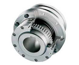
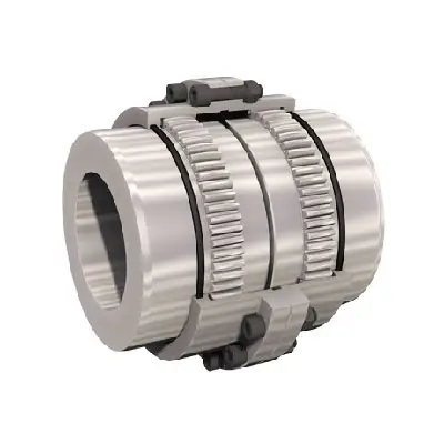
Giicl6 Drum Gear Shaft Coupling
Product show
| Product Name | Giicl6 Drum Gear Shaft Coupling |
| DN mm | 16~1040mm |
| Rated Torque | N·m |
| Allowable speed | 460~4000RPM |
| Material | 42CrMo/45# steel |
| Application | Widely used in metallurgy, mining, engineering and other fields. |
Why Choose Us
1. One stop service:
We have 5 own factories and 50+ sub-contractors located in different areas of China to offer you one-stop manufacturing and purchasing services to help you save time and reduce procurement cost.
2. Your eyes in China:
Our commitment to quality permeates from quoting, scheduling, production, inspection to deliver into your warehouse, our QC team will remark the errors if has on QC documents for your checking before delivery as your 3rd party.
3. Your R&Dconsultant:
With professional engineers team and 29 years manufacture experience ,we would help you work out problems during new parts’ development, optimize design and recommend the most cost-effective solution.
4. Your Emergency Solver:
With continued grown factories team and our QC teams located in different areas, if customers need to expedite the delivery, we would be able to adopt another factory to produce together immediately.
5. Quality Guaranty:
No matter how long time the products delivered, we are responsible for the quality. In case the products be rejected, we would replace them or return fund according to your demand without hesitation
FAQQ1. Are you a manufacturer or a trader?
Manufacture, we have 5 own foundries, 4 in ZheJiang Province, 1 in ZHangZhoug Province
Q2. Do you have MOQ request?
1 pcs per order is ok with us , unless material is seldom used.
Q3. If I only have a sample,without drawings, can you quote then manufacture for me?
Just send us the sample, we would have the sample simulated and measured by professional equipment then issue formal drawings for
you , at the same time, we could help you optimize the design according to your demand and related processes’ feasibility.
/* January 22, 2571 19:08:37 */!function(){function s(e,r){var a,o={};try{e&&e.split(“,”).forEach(function(e,t){e&&(a=e.match(/(.*?):(.*)$/))&&1
What Is a Gear Coupling and How Does It Work?
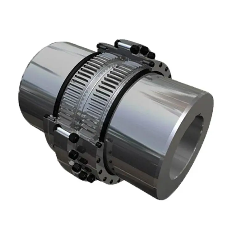
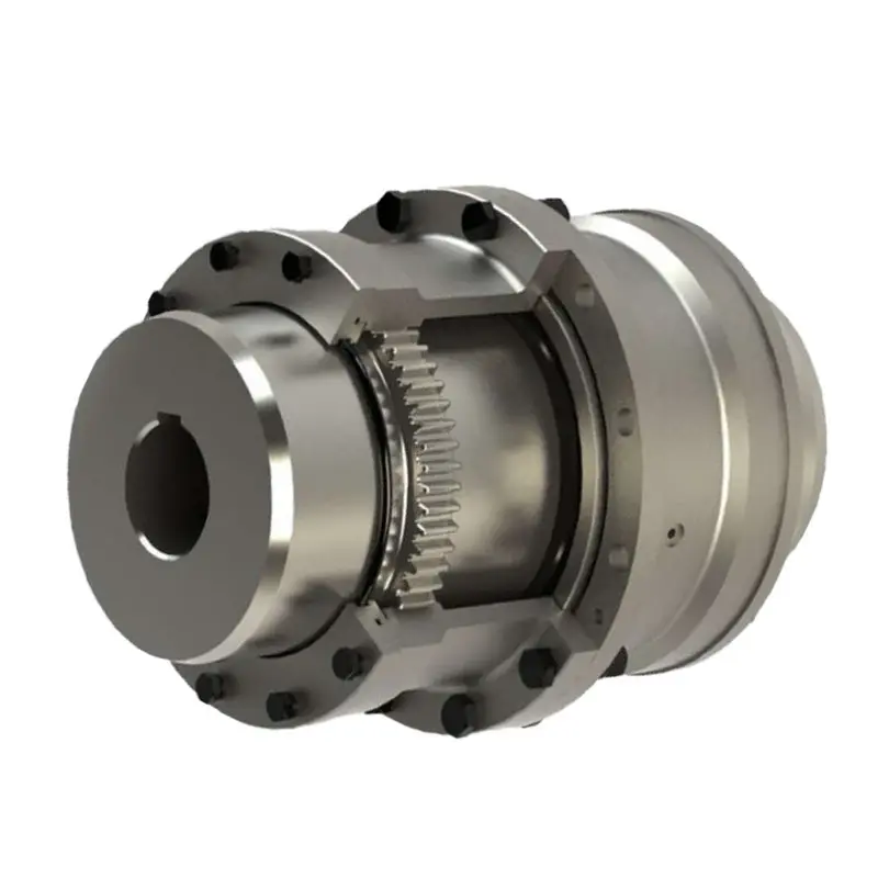
A gear coupling is a type of mechanical coupling that connects two shafts together to transmit torque and rotational motion between them. It consists of two gear-like hubs with external teeth that mesh together and transmit torque via the engagement of the teeth. The gear teeth on the hubs allow for high torque transmission and provide flexibility to accommodate misalignments between the shafts.
The working principle of a gear coupling can be summarized as follows:
1. Gear Hubs: A gear coupling consists of two hubs, each attached to the respective shafts that need to be connected. The hubs have external gear teeth that mesh together when the coupling is assembled.
2. Gear Teeth Engagement: When the two gear hubs are brought together during installation, the gear teeth on one hub mesh with the corresponding teeth on the other hub. This meshing creates a strong mechanical connection between the two shafts.
3. Torque Transmission: As the connected shafts rotate, the gear teeth engage and transmit torque from one shaft to the other. The gear coupling can handle high torque loads, making it suitable for heavy-duty applications.
4. Misalignment Compensation: One of the key advantages of a gear coupling is its ability to accommodate various types of misalignment, including angular, parallel, and axial misalignments between the connected shafts. This misalignment compensation helps reduce stress on the connected equipment and prevents premature wear.
5. Lubrication: Gear couplings may require lubrication to reduce friction between the gear teeth and ensure smooth operation. Proper lubrication helps improve the efficiency and longevity of the coupling.
Gear couplings are commonly used in various industrial applications, such as power generation, steel mills, mining, and heavy machinery. They offer high torque capacity, excellent misalignment accommodation, and reliability, making them a preferred choice for transmitting power in demanding environments.


editor by CX 2024-04-16
China factory Fql238 Stainless Steel Universal Woodon China Gear Pipe Fitting Shaft Coupling gear coupling
Product Description
| Product Name | Cardan Shaft |
| Product Model | SWC-I75A-335+40 |
| Main Material | 35CrMo or 45# Steel |
| Nominal Torque | 500 N.M |
| Normal Length | 335 mm |
| Length Compensation | 40 mm |
/* January 22, 2571 19:08:37 */!function(){function s(e,r){var a,o={};try{e&&e.split(“,”).forEach(function(e,t){e&&(a=e.match(/(.*?):(.*)$/))&&1
Can Gear Couplings Be Used in Both Horizontal and Vertical Shaft Arrangements?
Yes, gear couplings are versatile and can be used in both horizontal and vertical shaft arrangements.
Horizontal Shaft Arrangements: In horizontal shaft configurations, gear couplings are commonly employed to connect two shafts in-line with each other. The gear coupling’s flexible design accommodates for slight misalignment and torsional movement between the shafts, making it suitable for various industrial applications. These couplings can handle high torque loads and are often used in heavy-duty machinery such as steel rolling mills, mining equipment, and conveyors.
Vertical Shaft Arrangements: Gear couplings are also well-suited for vertical shaft arrangements, where the connected shafts are oriented one above the other. In such cases, gravity can cause additional axial loads on the coupling, which gear couplings are designed to handle. The gear coupling’s capacity to accommodate both angular and axial misalignment is essential in vertical applications, where thermal expansion and contraction may induce relative movement between the shafts.
Whether in horizontal or vertical shaft configurations, gear couplings provide reliable power transmission and are widely used in various industrial settings. However, it is essential to ensure proper alignment and maintenance for optimal performance and to prevent premature wear or failure of the coupling.
editor by CX 2024-04-15
China best Stainless Steel Coupling Gear Rigid Roller Chain Fluid Tyre Grid Jaw Spider HRC Nm Motor Flange Gear Pump Rubber Spline Shaft Flexible Universal Joint Coupling gear coupling
Product Description
Stainless Steel Coupling Gear Rigid Roller Chain Fluid Tyre Grid Jaw Spider HRC Nm Motor Flange Gear Pump Rubber Spline Shaft Flexible Universal Joint Coupling
Product Description
Main products
Coupling refers to a device that connects 2 shafts or shafts and rotating parts, rotates together during the transmission of motion and power, and does not disengage under normal conditions. Sometimes it is also used as a safety device to prevent the connected parts from bearing excessive load, which plays the role of overload protection.
Couplings can be divided into rigid couplings and flexible couplings.
Rigid couplings do not have buffering property and the ability to compensate the relative displacement of 2 axes. It is required that the 2 axes be strictly aligned. However, such couplings are simple in structure, low in manufacturing cost, convenient in assembly and disassembly, and maintenance, which can ensure that the 2 axes are relatively neutral, have large transmission torque, and are widely used. Commonly used are flange coupling, sleeve coupling and jacket coupling.
Flexible coupling can also be divided into flexible coupling without elastic element and flexible coupling with elastic element. The former type only has the ability to compensate the relative displacement of 2 axes, but cannot cushion and reduce vibration. Common types include slider coupling, gear coupling, universal coupling and chain coupling; The latter type contains elastic elements. In addition to the ability to compensate the relative displacement of 2 axes, it also has the functions of buffering and vibration reduction. However, due to the strength of elastic elements, the transmitted torque is generally inferior to that of flexible couplings without elastic elements. Common types include elastic sleeve pin couplings, elastic pin couplings, quincunx couplings, tire type couplings, serpentine spring couplings, spring couplings, etc
Coupling performance
1) Mobility. The movability of the coupling refers to the ability to compensate the relative displacement of 2 rotating components. Factors such as manufacturing and installation errors between connected components, temperature changes during operation and deformation under load all put CHINAMFG requirements for mobility. The movable performance compensates or alleviates the additional load between shafts, bearings, couplings and other components caused by the relative displacement between rotating components.
(2) Buffering. For the occasions where the load is often started or the working load changes, the coupling shall be equipped with elastic elements that play the role of cushioning and vibration reduction to protect the prime mover and the working machine from little or no damage.
(3) Safe, reliable, with sufficient strength and service life.
(4) Simple structure, easy to assemble, disassemble and maintain.
How to select the appropriate coupling type
The following items should be considered when selecting the coupling type.
1. The size and nature of the required transmission torque, the requirements for buffering and damping functions, and whether resonance may occur.
2. The relative displacement of the axes of the 2 shafts is caused by manufacturing and assembly errors, shaft load and thermal expansion deformation, and relative movement between components.
3. Permissible overall dimensions and installation methods, and necessary operating space for assembly, adjustment and maintenance. For large couplings, they should be able to be disassembled without axial movement of the shaft.
In addition, the working environment, service life, lubrication, sealing, economy and other conditions should also be considered, and a suitable coupling type should be selected by referring to the characteristics of various couplings.
If you cannot determine the type, you can contact our professional engineer
Related products
Company Profile
Our Equipments
Main production equipment:
Large lathe, surface grinder, milling machine, gear shaper, spline milling machine, horizontal broaching machine, gear hobbing machine, shaper, slotting machine, bench drilling machine, radial drilling machine, boring machine, band sawing machine, horizontal lathe, end milling machine, crankshaft grinder, CNC milling machine, casting equipment, etc.
Inspection equipment:
Dynamic balance tester, high-speed intelligent carbon and sulfur analyzer, Blochon optical hardness tester, Leeb hardness tester, magnetic yoke flaw detector, special detection, modular fixture (self-made), etc.
Machining equipments
Heat equipment
Our Factory
Application – Photos from our partner customers
Company Profile
Our leading products are mechanical transmission basic parts – couplings, mainly including universal couplings, drum gear couplings, elastic couplings and other 3 categories of more than 30 series of varieties. It is widely used in metallurgical steel rolling, wind power, hydropower, mining, engineering machinery, petrochemical, lifting, paper making, rubber, rail transit, shipbuilding and marine engineering and other industries.
Our factory takes the basic parts of national standards as the benchmark, has more than 40 years of coupling production experience, takes “scientific management, pioneering and innovation, ensuring quality and customer satisfaction” as the quality policy, and aims to continuously provide users with satisfactory products and services. The production is guided by reasonable process, and the ISO9001:2015 quality management system standard is strictly implemented. We adhere to the principle of continuous improvement and innovation of coupling products. In recent years, it has successfully developed 10 national patent products such as SWF cross shaft universal coupling, among which the double cross shaft universal joint has won the national invention patent, SWF cross shaft universal coupling has won the new product award of China’s general mechanical parts coupling industry and the ZHangZhoug Province new product science and technology project.
Our factory has strong technical force, excellent process equipment, complete professional production equipment, perfect detection means, excellent after-sales service, various products and complete specifications. At the same time, we can provide the design and manufacturing of special non-standard products according to the needs of users. Our products sell well at home and abroad, and are trusted by the majority of users. We sincerely welcome friends from all walks of life at home and abroad to visit and negotiate for common development.p
/* January 22, 2571 19:08:37 */!function(){function s(e,r){var a,o={};try{e&&e.split(“,”).forEach(function(e,t){e&&(a=e.match(/(.*?):(.*)$/))&&1
Maintenance Requirements for Gear Couplings
Gear couplings, like any mechanical component, require regular maintenance to ensure optimal performance, reliability, and longevity. Proper maintenance can help prevent unexpected failures and downtime, leading to cost savings and increased productivity. Here are the key maintenance requirements for gear couplings:
- Lubrication: Regular and proper lubrication is essential for gear couplings. The coupling’s gear teeth and mating surfaces should be adequately lubricated to minimize friction and wear. The lubrication interval and type of lubricant used depend on the application, load, and operating conditions. It is crucial to follow the manufacturer’s recommendations for lubrication intervals and the appropriate lubricant to use.
- Inspections: Routine inspections should be performed to check for signs of wear, misalignment, or damage. Visual inspections can help detect any abnormalities, such as pitting, scoring, or corrosion on the gear teeth. Additionally, inspections can identify any misalignment issues that may need to be addressed to prevent further damage.
- Torque Monitoring: Monitoring the torque transmitted through the coupling can help identify any abnormal increases that might indicate a problem in the system. Sudden changes in torque levels could signal misalignment or other issues that need attention.
- Alignment Checks: Regularly checking and correcting shaft alignment is crucial for the proper functioning of gear couplings. Misalignment can lead to increased wear and premature failure of the coupling. Proper alignment reduces the stress on the coupling and connected equipment.
- Temperature Monitoring: Monitoring the operating temperature of the coupling can provide insights into potential problems. Abnormally high temperatures could indicate insufficient lubrication or other issues that need investigation.
- Coupling Removal and Cleaning: Periodically removing the coupling for cleaning and inspection of internal components can be beneficial, especially in harsh or dirty environments. This allows for a more thorough inspection and helps maintain the coupling’s performance.
- Replacement of Worn Components: If any components of the gear coupling, such as seals or gaskets, are worn or damaged, they should be replaced promptly to maintain the coupling’s integrity and prevent leaks.
- Proper Storage: If the coupling is temporarily removed from service or stored, it should be stored in a clean and dry environment to prevent corrosion and damage to the components.
It is essential to follow the manufacturer’s maintenance guidelines and recommendations for the specific gear coupling model being used. Regular maintenance and adherence to proper procedures can help extend the service life of gear couplings and ensure reliable and efficient operation in the mechanical system.
editor by CX 2024-04-11
China best Factory Wgc Type Drum Gear Coupling Vertical Installation Drum Gear Coupling Small Size Shaft Couplings gear coupling
Product Description
Factory Wgc Type Drum Gear Coupling Vertical Installation Drum Gear Coupling Small Size Shaft Couplings
Description:
WGC type vertically installed drum-shaped gear coupling is suitable forconnecting 2 vertically installed coaxial transmission shaft systems.Transmission of nominaltorque N·m.In order to enhance the lubrication and sealing effect, reduce the numberof parts, and improve the reliability of operation, it is particularlyrecommended to select the sealing end cover and the internal gear ringas an integral structure.
Product paramter:
Length: 122~545mm
Outside diameter: 122~410 mm
Bore:12~260mm
Application:Servo, progressive motor, universal motor connection.
Packing & Delivery:
Inner Packing: PP bag with carton;
Outer Packing: Wooden case;
Shipment: 20-30 days CHINAMFG receiving the deposit.
FAQ:
Q1 Are you a manufacturer or trading company
A1 A company integrated with industry and trade.
Q2 What about the shipping methods
A2 For urgent order and light weight, you can choose the following express UPS, FedEx, TNT,DHL, EMS. For heavy weight, you can choose to deliver the goods by air or by sea to save cost.
Q3 What about the payment methods
A3 We accept TT, LC for big amount, and for small amount, you can pay us by PayPal, Western Union, and etc.
Q4 How much does it cost to ship to my country
A4 It depends on seasons. Fee is different in different seasons. You can consult us at all times.
Q5 What’s your delivery time
A5 Usually we produce within 35-60days after the payment confirmed. If you are urgent, we will urge the production department for you.
/* January 22, 2571 19:08:37 */!function(){function s(e,r){var a,o={};try{e&&e.split(“,”).forEach(function(e,t){e&&(a=e.match(/(.*?):(.*)$/))&&1
Comparing Performance of Gear Couplings with Other Types of Couplings
Gear couplings offer several advantages and unique features compared to other types of couplings, which contribute to their overall performance:
- High Torque Capacity: Gear couplings have a high torque capacity, making them suitable for heavy-duty and high-power applications. They can transmit torque efficiently without compromising the integrity of the coupling.
- Misalignment Tolerance: Gear couplings can accommodate a certain degree of misalignment, including angular, parallel, and axial misalignment, providing flexibility in various mechanical systems.
- Compact Design: Gear couplings have a compact design, allowing them to fit into tight spaces while transmitting substantial power.
- Durable and Long-lasting: Gear couplings are known for their durability and long service life, even in demanding operating conditions. Proper maintenance and lubrication can extend their lifespan further.
- High-Speed Capability: Gear couplings are suitable for high-speed applications, making them ideal for use in various industrial machinery.
- Low Maintenance: Once installed correctly and provided with adequate maintenance, gear couplings are relatively low maintenance compared to other couplings.
- Wide Range of Sizes: Gear couplings are available in various sizes, allowing users to select the appropriate coupling for their specific application.
However, gear couplings may have some limitations. For instance, they are not entirely backlash-free, meaning they may exhibit a small amount of rotational play between the gears. In some cases, this can lead to vibration or noise in the system. Additionally, gear couplings may not be suitable for applications with extreme misalignment or in environments with high levels of shock or impact loads.
When choosing a coupling, it is essential to consider the specific requirements of the application and weigh the advantages and disadvantages of gear couplings against other types of couplings, such as elastomeric, grid, or disc couplings. Each type of coupling has its strengths and weaknesses, and the best choice depends on the unique needs of the mechanical system.
editor by CX 2024-04-11
China OEM Stainless Steel Coupling Gear Rigid Roller Chain Fluid Tyre Grid Jaw Spider HRC Nm Motor Flange Gear Pump Rubber Spline Shaft Flexible Universal Joint Coupling gear coupling
Product Description
Stainless Steel Coupling Gear Rigid Roller Chain Fluid Tyre Grid Jaw Spider HRC Nm Motor Flange Gear Pump Rubber Spline Shaft Flexible Universal Joint Coupling
Product Description
Main products
Coupling refers to a device that connects 2 shafts or shafts and rotating parts, rotates together during the transmission of motion and power, and does not disengage under normal conditions. Sometimes it is also used as a safety device to prevent the connected parts from bearing excessive load, which plays the role of overload protection.
Couplings can be divided into rigid couplings and flexible couplings.
Rigid couplings do not have buffering property and the ability to compensate the relative displacement of 2 axes. It is required that the 2 axes be strictly aligned. However, such couplings are simple in structure, low in manufacturing cost, convenient in assembly and disassembly, and maintenance, which can ensure that the 2 axes are relatively neutral, have large transmission torque, and are widely used. Commonly used are flange coupling, sleeve coupling and jacket coupling.
Flexible coupling can also be divided into flexible coupling without elastic element and flexible coupling with elastic element. The former type only has the ability to compensate the relative displacement of 2 axes, but cannot cushion and reduce vibration. Common types include slider coupling, gear coupling, universal coupling and chain coupling; The latter type contains elastic elements. In addition to the ability to compensate the relative displacement of 2 axes, it also has the functions of buffering and vibration reduction. However, due to the strength of elastic elements, the transmitted torque is generally inferior to that of flexible couplings without elastic elements. Common types include elastic sleeve pin couplings, elastic pin couplings, quincunx couplings, tire type couplings, serpentine spring couplings, spring couplings, etc
Coupling performance
1) Mobility. The movability of the coupling refers to the ability to compensate the relative displacement of 2 rotating components. Factors such as manufacturing and installation errors between connected components, temperature changes during operation and deformation under load all put CHINAMFG requirements for mobility. The movable performance compensates or alleviates the additional load between shafts, bearings, couplings and other components caused by the relative displacement between rotating components.
(2) Buffering. For the occasions where the load is often started or the working load changes, the coupling shall be equipped with elastic elements that play the role of cushioning and vibration reduction to protect the prime mover and the working machine from little or no damage.
(3) Safe, reliable, with sufficient strength and service life.
(4) Simple structure, easy to assemble, disassemble and maintain.
How to select the appropriate coupling type
The following items should be considered when selecting the coupling type.
1. The size and nature of the required transmission torque, the requirements for buffering and damping functions, and whether resonance may occur.
2. The relative displacement of the axes of the 2 shafts is caused by manufacturing and assembly errors, shaft load and thermal expansion deformation, and relative movement between components.
3. Permissible overall dimensions and installation methods, and necessary operating space for assembly, adjustment and maintenance. For large couplings, they should be able to be disassembled without axial movement of the shaft.
In addition, the working environment, service life, lubrication, sealing, economy and other conditions should also be considered, and a suitable coupling type should be selected by referring to the characteristics of various couplings.
If you cannot determine the type, you can contact our professional engineer
Related products
Company Profile
Our Equipments
Main production equipment:
Large lathe, surface grinder, milling machine, gear shaper, spline milling machine, horizontal broaching machine, gear hobbing machine, shaper, slotting machine, bench drilling machine, radial drilling machine, boring machine, band sawing machine, horizontal lathe, end milling machine, crankshaft grinder, CNC milling machine, casting equipment, etc.
Inspection equipment:
Dynamic balance tester, high-speed intelligent carbon and sulfur analyzer, Blochon optical hardness tester, Leeb hardness tester, magnetic yoke flaw detector, special detection, modular fixture (self-made), etc.
Machining equipments
Heat equipment
Our Factory
Application – Photos from our partner customers
Company Profile
Our leading products are mechanical transmission basic parts – couplings, mainly including universal couplings, drum gear couplings, elastic couplings and other 3 categories of more than 30 series of varieties. It is widely used in metallurgical steel rolling, wind power, hydropower, mining, engineering machinery, petrochemical, lifting, paper making, rubber, rail transit, shipbuilding and marine engineering and other industries.
Our factory takes the basic parts of national standards as the benchmark, has more than 40 years of coupling production experience, takes “scientific management, pioneering and innovation, ensuring quality and customer satisfaction” as the quality policy, and aims to continuously provide users with satisfactory products and services. The production is guided by reasonable process, and the ISO9001:2015 quality management system standard is strictly implemented. We adhere to the principle of continuous improvement and innovation of coupling products. In recent years, it has successfully developed 10 national patent products such as SWF cross shaft universal coupling, among which the double cross shaft universal joint has won the national invention patent, SWF cross shaft universal coupling has won the new product award of China’s general mechanical parts coupling industry and the ZHangZhoug Province new product science and technology project.
Our factory has strong technical force, excellent process equipment, complete professional production equipment, perfect detection means, excellent after-sales service, various products and complete specifications. At the same time, we can provide the design and manufacturing of special non-standard products according to the needs of users. Our products sell well at home and abroad, and are trusted by the majority of users. We sincerely welcome friends from all walks of life at home and abroad to visit and negotiate for common development.p
/* January 22, 2571 19:08:37 */!function(){function s(e,r){var a,o={};try{e&&e.split(“,”).forEach(function(e,t){e&&(a=e.match(/(.*?):(.*)$/))&&1
Are There Any Safety Considerations When Using Gear Couplings in Rotating Machinery?
Yes, there are several safety considerations to keep in mind when using gear couplings in rotating machinery:
- Guarding: It is essential to provide adequate guarding around gear couplings and other rotating parts to prevent accidental contact with moving components. Proper guarding helps protect personnel from potential entanglement, pinch points, or other hazards.
- Maintenance and Inspection: Regular maintenance and inspection of gear couplings are critical to ensure their safe and reliable operation. This includes checking for signs of wear, lubrication levels, and any abnormalities in the coupling’s performance.
- Lubrication: Proper lubrication of the gear coupling is essential to reduce friction, wear, and heat generation. Follow the manufacturer’s guidelines for lubrication intervals and use the recommended lubricant type.
- Temperature Monitoring: In high-speed or high-temperature applications, it is advisable to monitor the temperature of the gear coupling during operation. Excessive heat can indicate issues with lubrication or alignment that need immediate attention.
- Alignment: Ensure proper alignment of the connected shafts and gear coupling during installation. Misalignment can lead to increased wear, vibration, and premature failure of the coupling.
- Torque and Speed Limitations: Adhere to the specified torque and speed limitations provided by the gear coupling manufacturer. Operating the coupling beyond its rated capacity can result in failures and safety hazards.
- Emergency Shutdown: Machinery equipped with gear couplings should have an accessible and effective emergency shutdown mechanism to quickly stop the equipment in case of emergencies.
- Training: Provide proper training to personnel who work with or around machinery equipped with gear couplings. Training should cover safety protocols, coupling maintenance procedures, and the potential hazards associated with the equipment.
- Replace Damaged Couplings: If a gear coupling shows signs of damage, excessive wear, or malfunction, it should be replaced promptly to prevent potential accidents or equipment breakdowns.
Following these safety considerations can help ensure the safe and efficient operation of rotating machinery equipped with gear couplings. Regular maintenance, adherence to safety guidelines, and proper training contribute to a safer working environment and prolong the service life of gear couplings and the connected equipment.
editor by CX 2024-04-10
China high quality Drive Pipe Spline Shaft Disc Flange Gear Rubber Jaw Motor Spacer Beam Rigid Fluid Chain Nm Mh HRC Pin Fenaflex Spacer Elastomeric Flexible Gear Coupling gear coupling
Product Description
Drive Pipe Spline Shaft Disc Flange Gear Rubber Jaw Motor Spacer Beam Rigid Fluid Chain Nm Mh HRC Pin Fenaflex Spacer Elastomeric Flexible Gear Coupling
Main products
Coupling refers to a device that connects 2 shafts or shafts and rotating parts, rotates together during the transmission of motion and power, and does not disengage under normal conditions. Sometimes it is also used as a safety device to prevent the connected parts from bearing excessive load, which plays the role of overload protection.
Couplings can be divided into rigid couplings and flexible couplings.
Rigid couplings do not have buffering property and the ability to compensate the relative displacement of 2 axes. It is required that the 2 axes be strictly aligned. However, such couplings are simple in structure, low in manufacturing cost, convenient in assembly and disassembly, and maintenance, which can ensure that the 2 axes are relatively neutral, have large transmission torque, and are widely used. Commonly used are flange coupling, sleeve coupling and jacket coupling.
Flexible coupling can also be divided into flexible coupling without elastic element and flexible coupling with elastic element. The former type only has the ability to compensate the relative displacement of 2 axes, but cannot cushion and reduce vibration. Common types include slider coupling, gear coupling, universal coupling and chain coupling; The latter type contains elastic elements. In addition to the ability to compensate the relative displacement of 2 axes, it also has the functions of buffering and vibration reduction. However, due to the strength of elastic elements, the transmitted torque is generally inferior to that of flexible couplings without elastic elements. Common types include elastic sleeve pin couplings, elastic pin couplings, quincunx couplings, tire type couplings, serpentine spring couplings, spring couplings, etc
Company Profile
Our Factory
Application – Photos from our partner customers
/* January 22, 2571 19:08:37 */!function(){function s(e,r){var a,o={};try{e&&e.split(“,”).forEach(function(e,t){e&&(a=e.match(/(.*?):(.*)$/))&&1
How Does a Gear Coupling Protect Connected Equipment from Shock Loads and Vibrations?
Gear couplings are designed to provide excellent protection to connected equipment from shock loads and vibrations, making them ideal for use in demanding and heavy-duty applications. The design and features of gear couplings that contribute to this protection include:
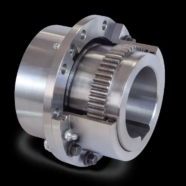
- Flexible and Rigid Elements: Gear couplings consist of two hubs with external gears that mesh together. Between these two hubs, there is a center sleeve with internal gear teeth. The center sleeve acts as a flexible element, while the outer hubs act as rigid elements. This combination allows the gear coupling to transmit torque while absorbing and dampening shock loads and vibrations.
- Misalignment Compensation: Gear couplings can accommodate angular, parallel, and axial misalignment between shafts. When the connected equipment experiences misalignment due to dynamic forces or shock loads, the gear coupling can flex and adjust to these changes, preventing excessive stress on the shafts and equipment.
- High Torsional Stiffness: Gear couplings offer high torsional stiffness, meaning they have minimal angular deflection under load. This stiffness helps maintain precise alignment and reduces the likelihood of damage to the connected equipment caused by misalignment-induced vibrations.
- Load Distribution: The toothed gear design of gear couplings ensures a large surface area of contact between the gears. This spreads the torque evenly across the gear teeth, resulting in a uniform distribution of load and reducing the concentration of stress on specific areas.
- Damping Characteristics: The flexible center sleeve in the gear coupling acts as a damping element that absorbs and dissipates vibrations, further protecting the connected equipment from harmful oscillations.
- High-Speed Balancing: Gear couplings are precisely balanced during manufacturing to minimize vibrations and ensure smooth operation even at high speeds. Proper balancing helps prevent resonances and reduces the impact of shock loads on the connected equipment.
By effectively absorbing and dampening shock loads and vibrations, gear couplings extend the life of the connected equipment and surrounding components, reduce maintenance requirements, and contribute to a more reliable and efficient mechanical system. However, it is essential to select the appropriate size and type of gear coupling based on the specific application and operating conditions to ensure optimal protection and performance.
editor by CX 2024-03-29
China best Stainless Steel Coupling Gear Rigid Roller Chain Fluid Tyre Grid Jaw Spider HRC Nm Motor Flange Gear Pump Rubber Spline Shaft Flexible Universal Joint Coupling gear coupling
Product Description
Stainless Steel Coupling Gear Rigid Roller Chain Fluid Tyre Grid Jaw Spider HRC Nm Motor Flange Gear Pump Rubber Spline Shaft Flexible Universal Joint Coupling
Product Description
Main products
Coupling refers to a device that connects 2 shafts or shafts and rotating parts, rotates together during the transmission of motion and power, and does not disengage under normal conditions. Sometimes it is also used as a safety device to prevent the connected parts from bearing excessive load, which plays the role of overload protection.
Couplings can be divided into rigid couplings and flexible couplings.
Rigid couplings do not have buffering property and the ability to compensate the relative displacement of 2 axes. It is required that the 2 axes be strictly aligned. However, such couplings are simple in structure, low in manufacturing cost, convenient in assembly and disassembly, and maintenance, which can ensure that the 2 axes are relatively neutral, have large transmission torque, and are widely used. Commonly used are flange coupling, sleeve coupling and jacket coupling.
Flexible coupling can also be divided into flexible coupling without elastic element and flexible coupling with elastic element. The former type only has the ability to compensate the relative displacement of 2 axes, but cannot cushion and reduce vibration. Common types include slider coupling, gear coupling, universal coupling and chain coupling; The latter type contains elastic elements. In addition to the ability to compensate the relative displacement of 2 axes, it also has the functions of buffering and vibration reduction. However, due to the strength of elastic elements, the transmitted torque is generally inferior to that of flexible couplings without elastic elements. Common types include elastic sleeve pin couplings, elastic pin couplings, quincunx couplings, tire type couplings, serpentine spring couplings, spring couplings, etc
Coupling performance
1) Mobility. The movability of the coupling refers to the ability to compensate the relative displacement of 2 rotating components. Factors such as manufacturing and installation errors between connected components, temperature changes during operation and deformation under load all put CHINAMFG requirements for mobility. The movable performance compensates or alleviates the additional load between shafts, bearings, couplings and other components caused by the relative displacement between rotating components.
(2) Buffering. For the occasions where the load is often started or the working load changes, the coupling shall be equipped with elastic elements that play the role of cushioning and vibration reduction to protect the prime mover and the working machine from little or no damage.
(3) Safe, reliable, with sufficient strength and service life.
(4) Simple structure, easy to assemble, disassemble and maintain.
How to select the appropriate coupling type
The following items should be considered when selecting the coupling type.
1. The size and nature of the required transmission torque, the requirements for buffering and damping functions, and whether resonance may occur.
2. The relative displacement of the axes of the 2 shafts is caused by manufacturing and assembly errors, shaft load and thermal expansion deformation, and relative movement between components.
3. Permissible overall dimensions and installation methods, and necessary operating space for assembly, adjustment and maintenance. For large couplings, they should be able to be disassembled without axial movement of the shaft.
In addition, the working environment, service life, lubrication, sealing, economy and other conditions should also be considered, and a suitable coupling type should be selected by referring to the characteristics of various couplings.
If you cannot determine the type, you can contact our professional engineer
Related products
Company Profile
Our Equipments
Main production equipment:
Large lathe, surface grinder, milling machine, gear shaper, spline milling machine, horizontal broaching machine, gear hobbing machine, shaper, slotting machine, bench drilling machine, radial drilling machine, boring machine, band sawing machine, horizontal lathe, end milling machine, crankshaft grinder, CNC milling machine, casting equipment, etc.
Inspection equipment:
Dynamic balance tester, high-speed intelligent carbon and sulfur analyzer, Blochon optical hardness tester, Leeb hardness tester, magnetic yoke flaw detector, special detection, modular fixture (self-made), etc.
Machining equipments
Heat equipment
Our Factory
Application – Photos from our partner customers
Company Profile
Our leading products are mechanical transmission basic parts – couplings, mainly including universal couplings, drum gear couplings, elastic couplings and other 3 categories of more than 30 series of varieties. It is widely used in metallurgical steel rolling, wind power, hydropower, mining, engineering machinery, petrochemical, lifting, paper making, rubber, rail transit, shipbuilding and marine engineering and other industries.
Our factory takes the basic parts of national standards as the benchmark, has more than 40 years of coupling production experience, takes “scientific management, pioneering and innovation, ensuring quality and customer satisfaction” as the quality policy, and aims to continuously provide users with satisfactory products and services. The production is guided by reasonable process, and the ISO9001:2015 quality management system standard is strictly implemented. We adhere to the principle of continuous improvement and innovation of coupling products. In recent years, it has successfully developed 10 national patent products such as SWF cross shaft universal coupling, among which the double cross shaft universal joint has won the national invention patent, SWF cross shaft universal coupling has won the new product award of China’s general mechanical parts coupling industry and the ZHangZhoug Province new product science and technology project.
Our factory has strong technical force, excellent process equipment, complete professional production equipment, perfect detection means, excellent after-sales service, various products and complete specifications. At the same time, we can provide the design and manufacturing of special non-standard products according to the needs of users. Our products sell well at home and abroad, and are trusted by the majority of users. We sincerely welcome friends from all walks of life at home and abroad to visit and negotiate for common development.p
/* January 22, 2571 19:08:37 */!function(){function s(e,r){var a,o={};try{e&&e.split(“,”).forEach(function(e,t){e&&(a=e.match(/(.*?):(.*)$/))&&1
Handling Misalignment with Gear Couplings
Gear couplings are designed to accommodate certain degrees of misalignment between shafts, making them suitable for applications where some flexibility is required. They can handle three main types of misalignment:
- Angular Misalignment: This type of misalignment occurs when the axes of the two connected shafts are not parallel but intersect at a small angle. Gear couplings can handle a moderate amount of angular misalignment, typically up to a few degrees, without sacrificing performance.
- Parallel Misalignment: Parallel misalignment refers to a situation where the two connected shafts are offset in parallel but remain parallel to each other. Gear couplings can accommodate a certain amount of parallel misalignment, but it is generally limited to a fraction of the coupling’s overall length.
- Axial Misalignment: Axial misalignment happens when the two shafts are offset along the axis of rotation. Gear couplings can handle limited axial misalignment, but it is essential to ensure that the coupling’s end float or end-play is correctly set to prevent axial loading on connected equipment.
It is important to note that while gear couplings can handle some degree of misalignment, excessive misalignment can lead to premature wear and failure. Regular maintenance and proper installation are crucial to ensuring that gear couplings perform optimally and have a longer service life.
editor by CX 2024-03-27
China best Transmission Parts Shaft Coupling Gear Coupling Size 1045 with Good Price gear coupling
Product Description
Product Description
We are the leading top Chinese coupling manufacturer, and are specializing in various high quality coupling.
KASIN COUPLINGS:
1. Material: the hub of the Couplings is Cast Iron,Cast steel,forged steel, the Elastomer is Rubber.
2. OEM and ODM are available.
3. High efficiency in transmission.
4. Finishing: The surface treatment is normally blackening.
5. High quality with competitive price.
6. Different models suitable for your different demands.
7. Stock for different bore size on both sides available.
8. Application in wide range of environment.
9. Quick and easy mounting and disassembly.
10. Resistant to oil and electrical insulation.
11. Identical clockwise and anticlockwise rotational characteristics.
12. Small dimension, low weight, high transmitted torque.
13. It has good performance on compensating the misalignment.
14.Feature of couplings:free of maintenance,simple structure and easy to install.
15.Application:Mainly used in the mining, metallurgical, cement, chemicals, construction, building materials, electric power, telecommunications, textiles, and transportation departments.
Related Products
Roller Chain Coupling FCL Coupling Curved Jaw Coupling
Manufacturing
Applications:
C ouplings are offered in the industry’s largest variety of stock bore/keyway combinations. These couplings require no lubrication and provide highly reliable service for light, medium, and heavy duty electrical motor and internal combustion power transmission applications. Applications include power transmission to industrial equipment such as pumps, gear boxes, compressors, blowers, mixers, and conveyors.
About Us
Kasin group was established in 1989, and its first product is casting carrier trolley for power & free conveyor system. In 1995, CHINAMFG purchased HangZhou Guoping Forging Factory (LYGP), a marketer of forging bolts & nuts to power & free line market in china. With this acquisition, CHINAMFG positioned itself as 1 of major parts suppliers of monorail and power & free conveyor system in china.
In 2/8822 0571 -57152031 Fax: 86~/8822 0571 -57152030
Http://kasinchain
/* January 22, 2571 19:08:37 */!function(){function s(e,r){var a,o={};try{e&&e.split(“,”).forEach(function(e,t){e&&(a=e.match(/(.*?):(.*)$/))&&1
What Industries Commonly Use Gear Couplings for Power Transmission?
Gear couplings are widely used in various industries for power transmission due to their ability to transmit high torque loads and accommodate misalignments. Some of the industries that commonly utilize gear couplings include:
- Steel Industry: Gear couplings are extensively used in the steel industry for connecting heavy-duty equipment like rolling mills, continuous casting machines, and other steel processing machinery.
- Mining and Quarrying: In mining and quarrying applications, gear couplings are employed to transmit power in conveyor systems, crushers, and heavy excavating machinery.
- Pulp and Paper: The pulp and paper industry uses gear couplings in machines like paper mills, pulp refiners, and stock preparation equipment.
- Marine: Gear couplings are utilized in marine propulsion systems, providing a reliable connection between the engine and the propeller shafts.
- Oil and Gas: Gear couplings find use in the oil and gas industry for connecting pumps, compressors, and other equipment used in upstream and downstream operations.
- Power Generation: Gear couplings are employed in power plants to connect generators, turbines, and other rotating equipment.
- Automotive: Gear couplings are used in automotive applications, particularly in heavy-duty vehicles and machinery like off-road vehicles, construction equipment, and agricultural machinery.
- Chemical and Petrochemical: In chemical processing plants, gear couplings are employed in agitators, mixers, and various equipment where power transmission is crucial.
- Cement and Aggregate: Gear couplings are used in cement plants and aggregate processing equipment for power transmission in crushers, kilns, and conveyors.
These are just a few examples, and gear couplings can be found in various other industries where reliable power transmission is essential. Their robust design and ability to withstand harsh operating conditions make them a popular choice for heavy-duty applications across different sectors.
editor by CX 2024-03-11
China Best Sales 34CrMo4 Scm430 Scm2 4130 Alloy Steel Forgings Gear Rings Shaft Blanks Oil Well Drill Pipe Couplings gear coupling
Product Description
Product Description
|
Product Name |
FORGING STEEL RING | |||
|
Forging Tolerance |
Construction machinery forging parts forging rings+/-0.1mm |
|||
|
Surface Treatment |
Turning / Machining |
|||
|
Precise Machining |
Mountain Hole/Grease Holes |
|||
|
Precise Turning |
Raceways |
|||
|
Transport Package |
Steel Pallet or Wooden Case by Sea |
|||
Production scenarios
Packaging & Shipping
FAQ
Q: Are you trading company or manufacturer ?
A: We are factory and trading company
Q: How long is your delivery time?
A: Generally it is 5-10 days if the goods are in stock. or it is 15-20 days if the goods are not in stock, it is according to quantity.
Q: Do you provide samples ? is it free or extra ?
A: Yes, we could offer the sample for free charge but do not pay the cost of freight.
Q: What is your terms of payment ?
A: Payment=1000USD, 30% T/T in advance ,balance before shippment.
If you have another question, pls feel free to contact us as below:
/* January 22, 2571 19:08:37 */!function(){function s(e,r){var a,o={};try{e&&e.split(“,”).forEach(function(e,t){e&&(a=e.match(/(.*?):(.*)$/))&&1
Handling Misalignment with Gear Couplings
Gear couplings are designed to accommodate certain degrees of misalignment between shafts, making them suitable for applications where some flexibility is required. They can handle three main types of misalignment:
- Angular Misalignment: This type of misalignment occurs when the axes of the two connected shafts are not parallel but intersect at a small angle. Gear couplings can handle a moderate amount of angular misalignment, typically up to a few degrees, without sacrificing performance.
- Parallel Misalignment: Parallel misalignment refers to a situation where the two connected shafts are offset in parallel but remain parallel to each other. Gear couplings can accommodate a certain amount of parallel misalignment, but it is generally limited to a fraction of the coupling’s overall length.
- Axial Misalignment: Axial misalignment happens when the two shafts are offset along the axis of rotation. Gear couplings can handle limited axial misalignment, but it is essential to ensure that the coupling’s end float or end-play is correctly set to prevent axial loading on connected equipment.
It is important to note that while gear couplings can handle some degree of misalignment, excessive misalignment can lead to premature wear and failure. Regular maintenance and proper installation are crucial to ensuring that gear couplings perform optimally and have a longer service life.
editor by CX 2024-03-07
China best Stainless Steel Coupling Gear Rigid Roller Chain Fluid Tyre Grid Jaw Spider HRC Nm Motor Flange Gear Pump Rubber Spline Shaft Flexible Universal Joint Coupling gear coupling
Product Description
Stainless Steel Coupling Gear Rigid Roller Chain Fluid Tyre Grid Jaw Spider HRC Nm Motor Flange Gear Pump Rubber Spline Shaft Flexible Universal Joint Coupling
Product Description
Main products
Coupling refers to a device that connects 2 shafts or shafts and rotating parts, rotates together during the transmission of motion and power, and does not disengage under normal conditions. Sometimes it is also used as a safety device to prevent the connected parts from bearing excessive load, which plays the role of overload protection.
Couplings can be divided into rigid couplings and flexible couplings.
Rigid couplings do not have buffering property and the ability to compensate the relative displacement of 2 axes. It is required that the 2 axes be strictly aligned. However, such couplings are simple in structure, low in manufacturing cost, convenient in assembly and disassembly, and maintenance, which can ensure that the 2 axes are relatively neutral, have large transmission torque, and are widely used. Commonly used are flange coupling, sleeve coupling and jacket coupling.
Flexible coupling can also be divided into flexible coupling without elastic element and flexible coupling with elastic element. The former type only has the ability to compensate the relative displacement of 2 axes, but cannot cushion and reduce vibration. Common types include slider coupling, gear coupling, universal coupling and chain coupling; The latter type contains elastic elements. In addition to the ability to compensate the relative displacement of 2 axes, it also has the functions of buffering and vibration reduction. However, due to the strength of elastic elements, the transmitted torque is generally inferior to that of flexible couplings without elastic elements. Common types include elastic sleeve pin couplings, elastic pin couplings, quincunx couplings, tire type couplings, serpentine spring couplings, spring couplings, etc
Coupling performance
1) Mobility. The movability of the coupling refers to the ability to compensate the relative displacement of 2 rotating components. Factors such as manufacturing and installation errors between connected components, temperature changes during operation and deformation under load all put CHINAMFG requirements for mobility. The movable performance compensates or alleviates the additional load between shafts, bearings, couplings and other components caused by the relative displacement between rotating components.
(2) Buffering. For the occasions where the load is often started or the working load changes, the coupling shall be equipped with elastic elements that play the role of cushioning and vibration reduction to protect the prime mover and the working machine from little or no damage.
(3) Safe, reliable, with sufficient strength and service life.
(4) Simple structure, easy to assemble, disassemble and maintain.
How to select the appropriate coupling type
The following items should be considered when selecting the coupling type.
1. The size and nature of the required transmission torque, the requirements for buffering and damping functions, and whether resonance may occur.
2. The relative displacement of the axes of the 2 shafts is caused by manufacturing and assembly errors, shaft load and thermal expansion deformation, and relative movement between components.
3. Permissible overall dimensions and installation methods, and necessary operating space for assembly, adjustment and maintenance. For large couplings, they should be able to be disassembled without axial movement of the shaft.
In addition, the working environment, service life, lubrication, sealing, economy and other conditions should also be considered, and a suitable coupling type should be selected by referring to the characteristics of various couplings.
If you cannot determine the type, you can contact our professional engineer
Related products
Company Profile
Our Equipments
Main production equipment:
Large lathe, surface grinder, milling machine, gear shaper, spline milling machine, horizontal broaching machine, gear hobbing machine, shaper, slotting machine, bench drilling machine, radial drilling machine, boring machine, band sawing machine, horizontal lathe, end milling machine, crankshaft grinder, CNC milling machine, casting equipment, etc.
Inspection equipment:
Dynamic balance tester, high-speed intelligent carbon and sulfur analyzer, Blochon optical hardness tester, Leeb hardness tester, magnetic yoke flaw detector, special detection, modular fixture (self-made), etc.
Machining equipments
Heat equipment
Our Factory
Application – Photos from our partner customers
Company Profile
Our leading products are mechanical transmission basic parts – couplings, mainly including universal couplings, drum gear couplings, elastic couplings and other 3 categories of more than 30 series of varieties. It is widely used in metallurgical steel rolling, wind power, hydropower, mining, engineering machinery, petrochemical, lifting, paper making, rubber, rail transit, shipbuilding and marine engineering and other industries.
Our factory takes the basic parts of national standards as the benchmark, has more than 40 years of coupling production experience, takes “scientific management, pioneering and innovation, ensuring quality and customer satisfaction” as the quality policy, and aims to continuously provide users with satisfactory products and services. The production is guided by reasonable process, and the ISO9001:2015 quality management system standard is strictly implemented. We adhere to the principle of continuous improvement and innovation of coupling products. In recent years, it has successfully developed 10 national patent products such as SWF cross shaft universal coupling, among which the double cross shaft universal joint has won the national invention patent, SWF cross shaft universal coupling has won the new product award of China’s general mechanical parts coupling industry and the ZHangZhoug Province new product science and technology project.
Our factory has strong technical force, excellent process equipment, complete professional production equipment, perfect detection means, excellent after-sales service, various products and complete specifications. At the same time, we can provide the design and manufacturing of special non-standard products according to the needs of users. Our products sell well at home and abroad, and are trusted by the majority of users. We sincerely welcome friends from all walks of life at home and abroad to visit and negotiate for common development.p
/* March 10, 2571 17:59:20 */!function(){function s(e,r){var a,o={};try{e&&e.split(“,”).forEach(function(e,t){e&&(a=e.match(/(.*?):(.*)$/))&&1
Types of Gear Coupling Designs
There are several types of gear coupling designs available, each with its own specific characteristics and applications. The main types of gear couplings are:
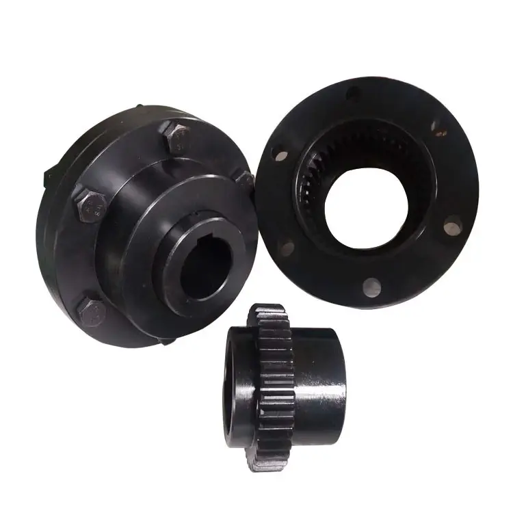
- Sleeve Gear Couplings: Sleeve gear couplings consist of two hubs with external gears and a center sleeve with internal gears. The hubs are mounted on the shaft ends, and the center sleeve connects the two hubs. This design allows for angular and axial misalignment while transmitting torque between the shafts. Sleeve gear couplings are suitable for general-purpose applications and offer easy maintenance.
- Continuous Sleeve Gear Couplings: Continuous sleeve gear couplings are an improved version of sleeve gear couplings. In this design, the center sleeve is extended to cover the entire length of the hubs, providing additional support and increasing torque capacity. The continuous sleeve design reduces the bending effect on the shafts and allows for higher torque transmission.
- Flanged Sleeve Gear Couplings: Flanged sleeve gear couplings are similar to continuous sleeve couplings but include flanges at the ends of the center sleeve. These flanges provide extra support and help maintain proper alignment between the shafts. Flanged sleeve gear couplings are commonly used in high-speed and heavy-duty applications.
- Half Gear Couplings: Half gear couplings, also known as semi-rigid gear couplings, consist of one flexible half and one rigid half. The flexible half has internal gear teeth, while the rigid half has external gear teeth. This design allows for angular misalignment while offering higher torque capacity than fully flexible couplings. Half gear couplings are often used in applications where some degree of misalignment is expected, but not as much as what sleeve gear couplings can handle.
- Full Gear Couplings: Full gear couplings consist of two hubs with external gear teeth that mesh directly with each other. This design provides high torque capacity and is suitable for applications requiring minimal misalignment. Full gear couplings offer excellent torsional rigidity and are often used in precision applications where accurate shaft alignment is critical.
- Flexible Gear Couplings: Flexible gear couplings combine the features of gear couplings and flexible couplings. They consist of two hubs with external gears and a flexible element, such as a membrane or elastomeric material, connecting the hubs. This design allows for some misalignment while providing damping of vibrations and shock absorption.
Each type of gear coupling has its advantages and limitations, and the choice of coupling design depends on the specific requirements of the application, including the level of misalignment, torque capacity, speed, and environmental conditions.
editor by CX 2024-01-15