Product Description
WGP Drum Gear Flexible Coupling With Brake Disc For Heavy Industrial Equipment
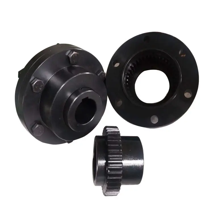
Description:
WGP Drum Gear Coupling With Brake Disc has a brake disc, brake disc can rotate speed by controlling the speed to adjust the machine. As shown in figure WGP with brake drum set type gear coupling is divided into I type and II type 2 forms, the only difference is that the brake disc is different.
WGP Drum Gear Coupling With Brake Disc is an improved type of gear coupling, consisting of inner gear and the same number of teeth of the flange half band coupling parts etc..
WGP Drum Gear Coupling With Brake Disc at work, 2 have the relative angular displacement, relative axial sliding periodic internal and external gear tooth surface, will inevitably lead to tooth wear and power consumption, therefore, the gear coupling needs to work in good condition and seal. The toothed coupling has small radial size and large load capacity. It is usually used for shafting transmission under low speed and heavy load conditions. The high accuracy and dynamic balancing gear coupling can be used for high speed transmission.
Features:
1. Double drum-shaped tooth structure, can compensate for a larger axis offset,
2. The brake disc is arranged at the passive end of the coupling, the weight of the brake disc and the working brake load and vibration are completely supported by the half coupling, thereby improving the meshing performance of the drum teeth during braking,
3. The maximum braking torque is not restricted by the structural strength of the coupling, safe and reliable,
4. Compact structure, brake disc cooling conditions are good,
5. Plug-in brake disc can be quickly be replaced without removing the device.
Applications:
Metallurgy, mining, lifting and transportation industries, petroleum, chemical, general machinery and other heavy machinery shaft drive.
Packing & shipping:
1 Prevent from damage.
2. As customers’ requirements, in perfect condition.
3. Delivery : As per contract delivery on time
4. Shipping : As per client request. We can accept CIF, Door to Door etc. or client authorized agent we supply all the necessary assistant.
FAQ:
Q 1: Are you a trading company or a manufacturer?
A: We are a professional manufacturer specializing in manufacturing various series of couplings.
Q 2:Can you do OEM?
Yes, we can. We can do OEM & ODM for all the customers with customized artworks in PDF or AI format.
Q 3:How long is your delivery time?
Generally, it is 20-30 days if the goods are not in stock. It is according to quantity.
Q 4: How long is your warranty?
A: Our Warranty is 12 months under normal circumstances.
Q 5: Do you have inspection procedures for coupling?
A:100% self-inspection before packing.
Q 6: Can I have a visit to your factory before the order?
A: Sure, welcome to visit our factory. /* January 22, 2571 19:08:37 */!function(){function s(e,r){var a,o={};try{e&&e.split(“,”).forEach(function(e,t){e&&(a=e.match(/(.*?):(.*)$/))&&1
What Is a Gear Coupling and How Does It Work?
A gear coupling is a type of mechanical coupling that connects two shafts together to transmit torque and rotational motion between them. It consists of two gear-like hubs with external teeth that mesh together and transmit torque via the engagement of the teeth. The gear teeth on the hubs allow for high torque transmission and provide flexibility to accommodate misalignments between the shafts.
The working principle of a gear coupling can be summarized as follows:
1. Gear Hubs: A gear coupling consists of two hubs, each attached to the respective shafts that need to be connected. The hubs have external gear teeth that mesh together when the coupling is assembled.
2. Gear Teeth Engagement: When the two gear hubs are brought together during installation, the gear teeth on one hub mesh with the corresponding teeth on the other hub. This meshing creates a strong mechanical connection between the two shafts.
3. Torque Transmission: As the connected shafts rotate, the gear teeth engage and transmit torque from one shaft to the other. The gear coupling can handle high torque loads, making it suitable for heavy-duty applications.
4. Misalignment Compensation: One of the key advantages of a gear coupling is its ability to accommodate various types of misalignment, including angular, parallel, and axial misalignments between the connected shafts. This misalignment compensation helps reduce stress on the connected equipment and prevents premature wear.
5. Lubrication: Gear couplings may require lubrication to reduce friction between the gear teeth and ensure smooth operation. Proper lubrication helps improve the efficiency and longevity of the coupling.
Gear couplings are commonly used in various industrial applications, such as power generation, steel mills, mining, and heavy machinery. They offer high torque capacity, excellent misalignment accommodation, and reliability, making them a preferred choice for transmitting power in demanding environments.


editor by CX 2024-04-19
China Custom Wgp Drum Gear Stainless Steel Flexible Coupling with Brake Disc for Heavy Industrial Equipment gear coupling
Product Description
WGP Drum Gear Flexible Coupling With Brake Disc For Heavy Industrial Equipment
Description:
WGP Drum Gear Coupling With Brake Disc has a brake disc, brake disc can rotate speed by controlling the speed to adjust the machine. As shown in figure WGP with brake drum set type gear coupling is divided into I type and II type 2 forms, the only difference is that the brake disc is different.
WGP Drum Gear Coupling With Brake Disc is an improved type of gear coupling, consisting of inner gear and the same number of teeth of the flange half band coupling parts etc..
WGP Drum Gear Coupling With Brake Disc at work, 2 have the relative angular displacement, relative axial sliding periodic internal and external gear tooth surface, will inevitably lead to tooth wear and power consumption, therefore, the gear coupling needs to work in good condition and seal. The toothed coupling has small radial size and large load capacity. It is usually used for shafting transmission under low speed and heavy load conditions. The high accuracy and dynamic balancing gear coupling can be used for high speed transmission.
Features:
1. Double drum-shaped tooth structure, can compensate for a larger axis offset,
2. The brake disc is arranged at the passive end of the coupling, the weight of the brake disc and the working brake load and vibration are completely supported by the half coupling, thereby improving the meshing performance of the drum teeth during braking,
3. The maximum braking torque is not restricted by the structural strength of the coupling, safe and reliable,
4. Compact structure, brake disc cooling conditions are good,
5. Plug-in brake disc can be quickly be replaced without removing the device.
Applications:
Metallurgy, mining, lifting and transportation industries, petroleum, chemical, general machinery and other heavy machinery shaft drive.
Packing & shipping:
1 Prevent from damage.
2. As customers’ requirements, in perfect condition.
3. Delivery : As per contract delivery on time
4. Shipping : As per client request. We can accept CIF, Door to Door etc. or client authorized agent we supply all the necessary assistant.
FAQ:
Q 1: Are you a trading company or a manufacturer?
A: We are a professional manufacturer specializing in manufacturing various series of couplings.
Q 2:Can you do OEM?
Yes, we can. We can do OEM & ODM for all the customers with customized artworks in PDF or AI format.
Q 3:How long is your delivery time?
Generally, it is 20-30 days if the goods are not in stock. It is according to quantity.
Q 4: How long is your warranty?
A: Our Warranty is 12 months under normal circumstances.
Q 5: Do you have inspection procedures for coupling?
A:100% self-inspection before packing.
Q 6: Can I have a visit to your factory before the order?
A: Sure, welcome to visit our factory. /* January 22, 2571 19:08:37 */!function(){function s(e,r){var a,o={};try{e&&e.split(“,”).forEach(function(e,t){e&&(a=e.match(/(.*?):(.*)$/))&&1
Types of Gear Coupling Designs
There are several types of gear coupling designs available, each with its own specific characteristics and applications. The main types of gear couplings are:
- Sleeve Gear Couplings: Sleeve gear couplings consist of two hubs with external gears and a center sleeve with internal gears. The hubs are mounted on the shaft ends, and the center sleeve connects the two hubs. This design allows for angular and axial misalignment while transmitting torque between the shafts. Sleeve gear couplings are suitable for general-purpose applications and offer easy maintenance.
- Continuous Sleeve Gear Couplings: Continuous sleeve gear couplings are an improved version of sleeve gear couplings. In this design, the center sleeve is extended to cover the entire length of the hubs, providing additional support and increasing torque capacity. The continuous sleeve design reduces the bending effect on the shafts and allows for higher torque transmission.
- Flanged Sleeve Gear Couplings: Flanged sleeve gear couplings are similar to continuous sleeve couplings but include flanges at the ends of the center sleeve. These flanges provide extra support and help maintain proper alignment between the shafts. Flanged sleeve gear couplings are commonly used in high-speed and heavy-duty applications.
- Half Gear Couplings: Half gear couplings, also known as semi-rigid gear couplings, consist of one flexible half and one rigid half. The flexible half has internal gear teeth, while the rigid half has external gear teeth. This design allows for angular misalignment while offering higher torque capacity than fully flexible couplings. Half gear couplings are often used in applications where some degree of misalignment is expected, but not as much as what sleeve gear couplings can handle.
- Full Gear Couplings: Full gear couplings consist of two hubs with external gear teeth that mesh directly with each other. This design provides high torque capacity and is suitable for applications requiring minimal misalignment. Full gear couplings offer excellent torsional rigidity and are often used in precision applications where accurate shaft alignment is critical.
- Flexible Gear Couplings: Flexible gear couplings combine the features of gear couplings and flexible couplings. They consist of two hubs with external gears and a flexible element, such as a membrane or elastomeric material, connecting the hubs. This design allows for some misalignment while providing damping of vibrations and shock absorption.
Each type of gear coupling has its advantages and limitations, and the choice of coupling design depends on the specific requirements of the application, including the level of misalignment, torque capacity, speed, and environmental conditions.
editor by CX 2024-04-17
China Standard Wgp Drum Gear Stainless Steel Flexible Coupling with Brake Disc for Heavy Industrial Equipment gear coupling
Product Description
WGP Drum Gear Flexible Coupling With Brake Disc For Heavy Industrial Equipment
Description:
WGP Drum Gear Coupling With Brake Disc has a brake disc, brake disc can rotate speed by controlling the speed to adjust the machine. As shown in figure WGP with brake drum set type gear coupling is divided into I type and II type 2 forms, the only difference is that the brake disc is different.
WGP Drum Gear Coupling With Brake Disc is an improved type of gear coupling, consisting of inner gear and the same number of teeth of the flange half band coupling parts etc..
WGP Drum Gear Coupling With Brake Disc at work, 2 have the relative angular displacement, relative axial sliding periodic internal and external gear tooth surface, will inevitably lead to tooth wear and power consumption, therefore, the gear coupling needs to work in good condition and seal. The toothed coupling has small radial size and large load capacity. It is usually used for shafting transmission under low speed and heavy load conditions. The high accuracy and dynamic balancing gear coupling can be used for high speed transmission.
Features:
1. Double drum-shaped tooth structure, can compensate for a larger axis offset,
2. The brake disc is arranged at the passive end of the coupling, the weight of the brake disc and the working brake load and vibration are completely supported by the half coupling, thereby improving the meshing performance of the drum teeth during braking,
3. The maximum braking torque is not restricted by the structural strength of the coupling, safe and reliable,
4. Compact structure, brake disc cooling conditions are good,
5. Plug-in brake disc can be quickly be replaced without removing the device.
Applications:
Metallurgy, mining, lifting and transportation industries, petroleum, chemical, general machinery and other heavy machinery shaft drive.
Packing & shipping:
1 Prevent from damage.
2. As customers’ requirements, in perfect condition.
3. Delivery : As per contract delivery on time
4. Shipping : As per client request. We can accept CIF, Door to Door etc. or client authorized agent we supply all the necessary assistant.
FAQ:
Q 1: Are you a trading company or a manufacturer?
A: We are a professional manufacturer specializing in manufacturing various series of couplings.
Q 2:Can you do OEM?
Yes, we can. We can do OEM & ODM for all the customers with customized artworks in PDF or AI format.
Q 3:How long is your delivery time?
Generally, it is 20-30 days if the goods are not in stock. It is according to quantity.
Q 4: How long is your warranty?
A: Our Warranty is 12 months under normal circumstances.
Q 5: Do you have inspection procedures for coupling?
A:100% self-inspection before packing.
Q 6: Can I have a visit to your factory before the order?
A: Sure, welcome to visit our factory. /* January 22, 2571 19:08:37 */!function(){function s(e,r){var a,o={};try{e&&e.split(“,”).forEach(function(e,t){e&&(a=e.match(/(.*?):(.*)$/))&&1
Are There Any Safety Considerations When Using Gear Couplings in Rotating Machinery?
Yes, there are several safety considerations to keep in mind when using gear couplings in rotating machinery:
- Guarding: It is essential to provide adequate guarding around gear couplings and other rotating parts to prevent accidental contact with moving components. Proper guarding helps protect personnel from potential entanglement, pinch points, or other hazards.
- Maintenance and Inspection: Regular maintenance and inspection of gear couplings are critical to ensure their safe and reliable operation. This includes checking for signs of wear, lubrication levels, and any abnormalities in the coupling’s performance.
- Lubrication: Proper lubrication of the gear coupling is essential to reduce friction, wear, and heat generation. Follow the manufacturer’s guidelines for lubrication intervals and use the recommended lubricant type.
- Temperature Monitoring: In high-speed or high-temperature applications, it is advisable to monitor the temperature of the gear coupling during operation. Excessive heat can indicate issues with lubrication or alignment that need immediate attention.
- Alignment: Ensure proper alignment of the connected shafts and gear coupling during installation. Misalignment can lead to increased wear, vibration, and premature failure of the coupling.
- Torque and Speed Limitations: Adhere to the specified torque and speed limitations provided by the gear coupling manufacturer. Operating the coupling beyond its rated capacity can result in failures and safety hazards.
- Emergency Shutdown: Machinery equipped with gear couplings should have an accessible and effective emergency shutdown mechanism to quickly stop the equipment in case of emergencies.
- Training: Provide proper training to personnel who work with or around machinery equipped with gear couplings. Training should cover safety protocols, coupling maintenance procedures, and the potential hazards associated with the equipment.
- Replace Damaged Couplings: If a gear coupling shows signs of damage, excessive wear, or malfunction, it should be replaced promptly to prevent potential accidents or equipment breakdowns.
Following these safety considerations can help ensure the safe and efficient operation of rotating machinery equipped with gear couplings. Regular maintenance, adherence to safety guidelines, and proper training contribute to a safer working environment and prolong the service life of gear couplings and the connected equipment.
editor by CX 2024-03-13
China supplier Wgc Drum Gear Elastic Coupling Industrial Transmission Good Quality Curved Teeth Drum Shape Gear Coupling gear coupling
Product Description
WGC drum gear coupling elastic coupling
Description:
WGC type vertically installed drum-shaped gear coupling is suitable forconnecting 2 vertically installed coaxial transmission shaft systems.Transmission of nominaltorque N·m.In order to enhance the lubrication and sealing effect, reduce the numberof parts, and improve the reliability of operation, it is particularlyrecommended to select the sealing end cover and the internal gear ringas an integral structure.
Product paramter:
Length: 122~545mm
Outside diameter: 122~410 mm
Bore:12~260mm
Application:Servo, progressive motor, universal motor connection.
Packing & Delivery:
Inner Packing: PP bag with carton;
Outer Packing: Wooden case;
Shipment: 20-30 days CHINAMFG receiving the deposit.
FAQ:
Q 1: Are you a trading company or a manufacturer?
A: We are a professional manufacturer specializing in manufacturing various series of couplings.
Q 2:Can you do OEM?
Yes, we can. We can do OEM & ODM for all the customers with customized artworks in PDF or AI format.
Q 3:How long is your delivery time?
Generally, it is 20-30 days if the goods are not in stock. It is according to quantity.
Q 4: How long is your warranty?
A: Our Warranty is 12 months under normal circumstances.
Q 5: Do you have inspection procedures for coupling?
A:100% self-inspection before packing.
Q 6: Can I have a visit to your factory before the order?
A: Sure, welcome to visit our factory.
/* January 22, 2571 19:08:37 */!function(){function s(e,r){var a,o={};try{e&&e.split(“,”).forEach(function(e,t){e&&(a=e.match(/(.*?):(.*)$/))&&1
Comparing Performance of Gear Couplings with Other Types of Couplings
Gear couplings offer several advantages and unique features compared to other types of couplings, which contribute to their overall performance:
- High Torque Capacity: Gear couplings have a high torque capacity, making them suitable for heavy-duty and high-power applications. They can transmit torque efficiently without compromising the integrity of the coupling.
- Misalignment Tolerance: Gear couplings can accommodate a certain degree of misalignment, including angular, parallel, and axial misalignment, providing flexibility in various mechanical systems.
- Compact Design: Gear couplings have a compact design, allowing them to fit into tight spaces while transmitting substantial power.
- Durable and Long-lasting: Gear couplings are known for their durability and long service life, even in demanding operating conditions. Proper maintenance and lubrication can extend their lifespan further.
- High-Speed Capability: Gear couplings are suitable for high-speed applications, making them ideal for use in various industrial machinery.
- Low Maintenance: Once installed correctly and provided with adequate maintenance, gear couplings are relatively low maintenance compared to other couplings.
- Wide Range of Sizes: Gear couplings are available in various sizes, allowing users to select the appropriate coupling for their specific application.
However, gear couplings may have some limitations. For instance, they are not entirely backlash-free, meaning they may exhibit a small amount of rotational play between the gears. In some cases, this can lead to vibration or noise in the system. Additionally, gear couplings may not be suitable for applications with extreme misalignment or in environments with high levels of shock or impact loads.
When choosing a coupling, it is essential to consider the specific requirements of the application and weigh the advantages and disadvantages of gear couplings against other types of couplings, such as elastomeric, grid, or disc couplings. Each type of coupling has its strengths and weaknesses, and the best choice depends on the unique needs of the mechanical system.
editor by CX 2024-03-10
China manufacturer Kc10020 Industrial Transmission Gear Reducer Conveyor Parts Chain Couplings gear coupling
Product Description
|
Chain |
Chain No. |
D Bore Dia | Dimension | Inertia
×10-3 kgf·m2 |
Approx Weight
kg |
Casing | |||||||||||||||||||||||||||||||||||||||||||||||||||||||||||||||||||||||||||||||||||||||||||||||||||||||||||
| Min mm | Max mm | L
mm |
I
mm |
S
mm |
d1 mm |
d2 mm |
C
mm |
Dimension | Approx Weight
kg |
||||||||||||||||||||||||||||||||||||||||||||||||||||||||||||||||||||||||||||||||||||||||||||||||||||||||
| A mm |
B mm |
||||||||||||||||||||||||||||||||||||||||||||||||||||||||||||||||||||||||||||||||||||||||||||||||||||||||||||||||
| KC-1571 | 1-0-0. p. 211. Retrieved 17 May 2-0-0. p. 86. Retrieved 30 January 2015. Green 1996, pp. 2337-2361 “ANSI G7 Standard Roller Chain – Tsubaki Europe”. Tsubaki Europe. Tsubakimoto Europe B.V. Retrieved 18 June 2. External links Wikimedia Commons has media related to Roller chains. The Complete Xihu (West Lake) Dis. to Chain Categories: Chain drivesMechanical power transmissionMechanical power control Why Choose Us
Materials Used in Manufacturing Gear CouplingsGear couplings are designed to transmit torque between shafts while accommodating misalignment. To ensure the durability and reliability of gear couplings, manufacturers use a variety of materials, each with its specific properties. Commonly used materials in manufacturing gear couplings include:
The choice of material depends on the application’s demands, including the torque, speed, environmental conditions, and budget considerations. Gear coupling manufacturers carefully select materials that will provide optimal performance and longevity while meeting the specific requirements of the intended application.
China best Kc5018 Industrial Transmission Gear Reducer Conveyor Parts Chain Couplings gear couplingProduct Description
Chain couplingsThe Chain coupling is composed of a duplex roller chain and a pair of coupling sprockets. The function of connection and detachment is done by the joint of chain. It has the characteristic of compact and powerful, excellent durability, safe and smart, simple installation and easy alignment. The Xihu (West Lake) Dis.hua Chain coupling is suitable for a wide range of coupling applications. Roller chain( Coupling Chains) Though Hans Renold is credited with inventing the roller chain in 1880, sketches by Leonardo da Vinci in the 16th century show a chain with a roller bearing.Coupling chains)Coupling chainsRoller chain or bush roller chain is the type of chain drive most commonly used for transmission of mechanical power on many kinds of domestic, industrial and agricultural machinery, including conveyors, wire- and tube-drawing machines, printing presses, cars, motorcycles, and bicycles. It consists of a series of short cylindrical rollers held together by side links. It is driven by a toothed wheel called a sprocket. It is a simple, reliable, and efficient[1] means of power transmission.
| ||||||||||||||||||||||||||||||||||||||||||||||||||||||||||||||||||||||||||||||||||||||||||||||||||||||||||||||||