Product Description
Flexible flex Fluid Chain Jaw flange Gear Rigid Spacer PIN HRC MH NM universal Fenaflex Oldham spline clamp tyre grid hydraulic servo motor shaft Coupling
Product Description
The function of Shaft coupling:
1. Shafts for connecting separately manufactured units such as motors and generators.
2. If any axis is misaligned.
3. Provides mechanical flexibility.
4. Absorb the transmission of impact load.
5. Prevent overload
We can provide the following couplings.
| Rigid coupling | Flange coupling | Oldham coupling |
| Sleeve or muff coupling | Gear coupling | Bellow coupling |
| Split muff coupling | Flexible coupling | Fluid coupling |
| Clamp or split-muff or compression coupling | Universal coupling | Variable speed coupling |
| Bushed pin-type coupling | Diaphragm coupling | Constant speed coupling |
Company Profile
We are an industrial company specializing in the production of couplings. It has 3 branches: steel casting, forging, and heat treatment. Main products: cross shaft universal coupling, drum gear coupling, non-metallic elastic element coupling, rigid coupling, etc.
The company mainly produces the industry standard JB3241-91 swap JB5513-91 swc. JB3242-93 swz series universal coupling with spider type. It can also design and produce various non-standard universal couplings, other couplings, and mechanical products for users according to special requirements. Currently, the products are mainly sold to major steel companies at home and abroad, the metallurgical steel rolling industry, and leading engine manufacturers, with an annual production capacity of more than 7000 sets.
The company’s quality policy is “quality for survival, variety for development.” In August 2000, the national quality system certification authority audited that its quality assurance system met the requirements of GB/T19002-1994 IDT ISO9002:1994 and obtained the quality system certification certificate with the registration number 0900B5711. It is the first enterprise in the coupling production industry in HangZhou City that passed the ISO9002 quality and constitution certification.
The company pursues the business purpose of “reliable quality, the supremacy of reputation, commitment to business and customer satisfaction” and welcomes customers at home and abroad to choose our products.
At the same time, the company has established long-term cooperative relations with many enterprises and warmly welcomes friends from all walks of life to visit, investigate and negotiate business!
How to use the coupling safely
The coupling is an intermediate connecting part of each motion mechanism, which directly impacts the regular operation of each motion mechanism. Therefore, attention must be paid to:
1. The coupling is not allowed to have more than the specified axis deflection and radial displacement so as not to affect its transmission performance.
2. The bolts of the LINS coupling shall not be loose or damaged.
3. Gear coupling and cross slide coupling shall be lubricated regularly, and lubricating grease shall be added every 2-3 months to avoid severe wear of gear teeth and serious consequences.
4. The tooth width contact length of gear coupling shall not be less than 70%; Its axial displacement shall not be more significant than 5mm
5. The coupling is not allowed to have cracks. If there are cracks, it needs to be replaced (they can be knocked with a small hammer and judged according to the sound).
6. The keys of LINS coupling shall be closely matched and shall not be loosened.
7. The tooth thickness of the gear coupling is worn. When the lifting mechanism exceeds 15% of the original tooth thickness, the operating mechanism exceeds 25%, and the broken tooth is also scrapped.
8. If the elastic ring of the pin coupling and the sealing ring of the gear coupling is damaged or aged, they should be replaced in time.
Certifications
Packaging & Shipping
/* January 22, 2571 19:08:37 */!function(){function s(e,r){var a,o={};try{e&&e.split(“,”).forEach(function(e,t){e&&(a=e.match(/(.*?):(.*)$/))&&1
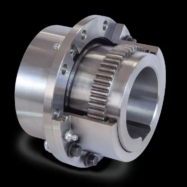
What Is a Gear Coupling and How Does It Work?
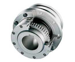
A gear coupling is a type of mechanical coupling that connects two shafts together to transmit torque and rotational motion between them. It consists of two gear-like hubs with external teeth that mesh together and transmit torque via the engagement of the teeth. The gear teeth on the hubs allow for high torque transmission and provide flexibility to accommodate misalignments between the shafts.
The working principle of a gear coupling can be summarized as follows:
1. Gear Hubs: A gear coupling consists of two hubs, each attached to the respective shafts that need to be connected. The hubs have external gear teeth that mesh together when the coupling is assembled.
2. Gear Teeth Engagement: When the two gear hubs are brought together during installation, the gear teeth on one hub mesh with the corresponding teeth on the other hub. This meshing creates a strong mechanical connection between the two shafts.
3. Torque Transmission: As the connected shafts rotate, the gear teeth engage and transmit torque from one shaft to the other. The gear coupling can handle high torque loads, making it suitable for heavy-duty applications.
4. Misalignment Compensation: One of the key advantages of a gear coupling is its ability to accommodate various types of misalignment, including angular, parallel, and axial misalignments between the connected shafts. This misalignment compensation helps reduce stress on the connected equipment and prevents premature wear.
5. Lubrication: Gear couplings may require lubrication to reduce friction between the gear teeth and ensure smooth operation. Proper lubrication helps improve the efficiency and longevity of the coupling.
Gear couplings are commonly used in various industrial applications, such as power generation, steel mills, mining, and heavy machinery. They offer high torque capacity, excellent misalignment accommodation, and reliability, making them a preferred choice for transmitting power in demanding environments.


editor by CX 2024-05-14
China Hot selling CHINAMFG Customized Hydraulic Yox Motor Hydraulic Gear Fluid Coupling, Yot Fluid Coupling gear coupling
Product Description
Densen customized hydraulic yox motor hydraulic gear fluid coupling,yot fluid coupling
| Product Name | Densen customized hydraulic yox motor hydraulic gear fluid coupling,yot fluid coupling |
| DN mm | 225~1312mm |
| Rated Torque | 2000~11950000N·m |
| Allowable speed | 1500~3000 RPM |
| Material | 35CrMo/ZG270/45# steel/Aluminum alloy |
| Application | Widely used in metallurgy, mining, engineering and other fields. |
Product show
Company Information
Equipment
Typical case of diaphragm coupling applied to variable frequency speed control equipment
JMB type coupling is applied to HangZhou Oilfield Thermal Power Plant
According to the requirements of HangZhou Electric Power Corporation, HangZhou Oilfield Thermal Power Plant should dynamically adjust the power generation according to the load of the power grid and market demand, and carry out the transformation of the frequency converter and the suction fan. The motor was originally a 1600KW, 730RPM non-frequency variable speed motor matched by HangZhou Motor Factory. The speed control mode after changing the frequency is manual control. Press the button speed to increase 10RPM or drop 10RPM. The coupling is still the original elastic decoupling coupling, and the elastic de-coupling coupling after frequency conversion is frequently damaged, which directly affects the normal power generation.
It is found through analysis that in the process of frequency conversion speed regulation, the pin of the coupling can not bear the inertia of the speed regulation process (the diameter of the fan impeller is 3.3 meters) and is cut off, which has great damage to the motor and the fan.
Later, they switched to the JMB460 double-diaphragm wheel-type coupling of our factory (patent number: ZL.99246247.9). After 1 hour of destructive experiment and more than 1 year of operation test, the equipment is running very well, and there is no Replace the diaphragm. 12 units have been rebuilt and the operation is in good condition.
Other Application Case
Spare parts
Packaging & Shipping
Contact us
/* January 22, 2571 19:08:37 */!function(){function s(e,r){var a,o={};try{e&&e.split(“,”).forEach(function(e,t){e&&(a=e.match(/(.*?):(.*)$/))&&1
Limitations and Disadvantages of Using Gear Couplings
While gear couplings offer many advantages, they also have some limitations and disadvantages that should be considered when selecting coupling solutions for specific applications:
- Cost: Gear couplings can be more expensive compared to other types of couplings, especially when precision machining or specialized materials are required. The initial investment might be higher, but the long-term benefits may outweigh the cost.
- Size and Weight: Gear couplings are generally larger and heavier than some other coupling types. This can impact the overall size and weight of the machinery, which may be a concern in applications with limited space or weight restrictions.
- Maintenance: Gear couplings require regular maintenance, including lubrication and periodic inspection to ensure proper functioning. Neglecting maintenance can lead to premature wear and failure.
- Backlash: Like other gear mechanisms, gear couplings may have some inherent backlash due to the clearance between gear teeth. This slight play can affect precision applications where accurate motion transmission is critical.
- Noise and Vibration: Gear couplings can generate more noise and vibration compared to flexible couplings, especially at higher speeds. This can be a concern in applications that require low-noise operation.
- Misalignment Tolerance: While gear couplings can handle moderate misalignment, they may not be as forgiving as flexible couplings in accommodating significant shaft misalignment.
Despite these limitations, gear couplings remain a popular choice for many applications, particularly in heavy-duty industrial settings where they excel in transmitting high torque and handling demanding conditions. Proper selection, installation, and maintenance can help mitigate some of the disadvantages, making gear couplings a reliable choice for power transmission in various industries.
editor by CX 2024-05-13
China OEM Stainless Steel Coupling Gear Rigid Roller Chain Fluid Tyre Grid Jaw Spider HRC Nm Motor Flange Gear Pump Rubber Spline Shaft Flexible Universal Joint Coupling gear coupling
Product Description
Stainless Steel Coupling Gear Rigid Roller Chain Fluid Tyre Grid Jaw Spider HRC Nm Motor Flange Gear Pump Rubber Spline Shaft Flexible Universal Joint Coupling
Product Description
Main products
Coupling refers to a device that connects 2 shafts or shafts and rotating parts, rotates together during the transmission of motion and power, and does not disengage under normal conditions. Sometimes it is also used as a safety device to prevent the connected parts from bearing excessive load, which plays the role of overload protection.
Couplings can be divided into rigid couplings and flexible couplings.
Rigid couplings do not have buffering property and the ability to compensate the relative displacement of 2 axes. It is required that the 2 axes be strictly aligned. However, such couplings are simple in structure, low in manufacturing cost, convenient in assembly and disassembly, and maintenance, which can ensure that the 2 axes are relatively neutral, have large transmission torque, and are widely used. Commonly used are flange coupling, sleeve coupling and jacket coupling.
Flexible coupling can also be divided into flexible coupling without elastic element and flexible coupling with elastic element. The former type only has the ability to compensate the relative displacement of 2 axes, but cannot cushion and reduce vibration. Common types include slider coupling, gear coupling, universal coupling and chain coupling; The latter type contains elastic elements. In addition to the ability to compensate the relative displacement of 2 axes, it also has the functions of buffering and vibration reduction. However, due to the strength of elastic elements, the transmitted torque is generally inferior to that of flexible couplings without elastic elements. Common types include elastic sleeve pin couplings, elastic pin couplings, quincunx couplings, tire type couplings, serpentine spring couplings, spring couplings, etc
Coupling performance
1) Mobility. The movability of the coupling refers to the ability to compensate the relative displacement of 2 rotating components. Factors such as manufacturing and installation errors between connected components, temperature changes during operation and deformation under load all put CHINAMFG requirements for mobility. The movable performance compensates or alleviates the additional load between shafts, bearings, couplings and other components caused by the relative displacement between rotating components.
(2) Buffering. For the occasions where the load is often started or the working load changes, the coupling shall be equipped with elastic elements that play the role of cushioning and vibration reduction to protect the prime mover and the working machine from little or no damage.
(3) Safe, reliable, with sufficient strength and service life.
(4) Simple structure, easy to assemble, disassemble and maintain.
How to select the appropriate coupling type
The following items should be considered when selecting the coupling type.
1. The size and nature of the required transmission torque, the requirements for buffering and damping functions, and whether resonance may occur.
2. The relative displacement of the axes of the 2 shafts is caused by manufacturing and assembly errors, shaft load and thermal expansion deformation, and relative movement between components.
3. Permissible overall dimensions and installation methods, and necessary operating space for assembly, adjustment and maintenance. For large couplings, they should be able to be disassembled without axial movement of the shaft.
In addition, the working environment, service life, lubrication, sealing, economy and other conditions should also be considered, and a suitable coupling type should be selected by referring to the characteristics of various couplings.
If you cannot determine the type, you can contact our professional engineer
Related products
Company Profile
Our Equipments
Main production equipment:
Large lathe, surface grinder, milling machine, gear shaper, spline milling machine, horizontal broaching machine, gear hobbing machine, shaper, slotting machine, bench drilling machine, radial drilling machine, boring machine, band sawing machine, horizontal lathe, end milling machine, crankshaft grinder, CNC milling machine, casting equipment, etc.
Inspection equipment:
Dynamic balance tester, high-speed intelligent carbon and sulfur analyzer, Blochon optical hardness tester, Leeb hardness tester, magnetic yoke flaw detector, special detection, modular fixture (self-made), etc.
Machining equipments
Heat equipment
Our Factory
Application – Photos from our partner customers
Company Profile
Our leading products are mechanical transmission basic parts – couplings, mainly including universal couplings, drum gear couplings, elastic couplings and other 3 categories of more than 30 series of varieties. It is widely used in metallurgical steel rolling, wind power, hydropower, mining, engineering machinery, petrochemical, lifting, paper making, rubber, rail transit, shipbuilding and marine engineering and other industries.
Our factory takes the basic parts of national standards as the benchmark, has more than 40 years of coupling production experience, takes “scientific management, pioneering and innovation, ensuring quality and customer satisfaction” as the quality policy, and aims to continuously provide users with satisfactory products and services. The production is guided by reasonable process, and the ISO9001:2015 quality management system standard is strictly implemented. We adhere to the principle of continuous improvement and innovation of coupling products. In recent years, it has successfully developed 10 national patent products such as SWF cross shaft universal coupling, among which the double cross shaft universal joint has won the national invention patent, SWF cross shaft universal coupling has won the new product award of China’s general mechanical parts coupling industry and the ZHangZhoug Province new product science and technology project.
Our factory has strong technical force, excellent process equipment, complete professional production equipment, perfect detection means, excellent after-sales service, various products and complete specifications. At the same time, we can provide the design and manufacturing of special non-standard products according to the needs of users. Our products sell well at home and abroad, and are trusted by the majority of users. We sincerely welcome friends from all walks of life at home and abroad to visit and negotiate for common development.p
/* January 22, 2571 19:08:37 */!function(){function s(e,r){var a,o={};try{e&&e.split(“,”).forEach(function(e,t){e&&(a=e.match(/(.*?):(.*)$/))&&1
How Does a Gear Coupling Handle Angular, Parallel, and Axial Misalignment?
Gear couplings are designed to handle various types of misalignment, including angular, parallel, and axial misalignment. Here’s how they handle each type:
- Angular Misalignment: Angular misalignment occurs when the two connected shafts are not collinear and form an angle with each other. Gear couplings can accommodate angular misalignment due to the flexibility of their gear teeth. The gear teeth allow a slight angular movement between the shafts without causing significant stress on the coupling.
- Parallel Misalignment: Parallel misalignment occurs when the two connected shafts are offset along their axis but remain parallel to each other. Gear couplings can handle parallel misalignment to some extent due to the slight axial movement allowed by the gear teeth. However, for larger parallel misalignments, special gear couplings with spacer elements or other features may be required.
- Axial Misalignment: Axial misalignment occurs when the two connected shafts are not in the same axial plane and have an offset along their length. Gear couplings can handle a certain degree of axial misalignment because the gear teeth can accommodate small axial movements without causing damage to the coupling or connected equipment.
The ability of gear couplings to handle misalignment is one of their key advantages over other types of couplings. The gear teeth act as flexible elements that can compensate for minor misalignments, reducing the stress and wear on the coupling and the connected equipment. However, it is essential to ensure that the misalignment remains within the allowable limits specified by the coupling manufacturer to maintain optimal performance and reliability.
editor by CX 2024-05-10
China Hot selling Factory Direct Sale Flexible Gear Coupling for Motor gear coupling
Product Description
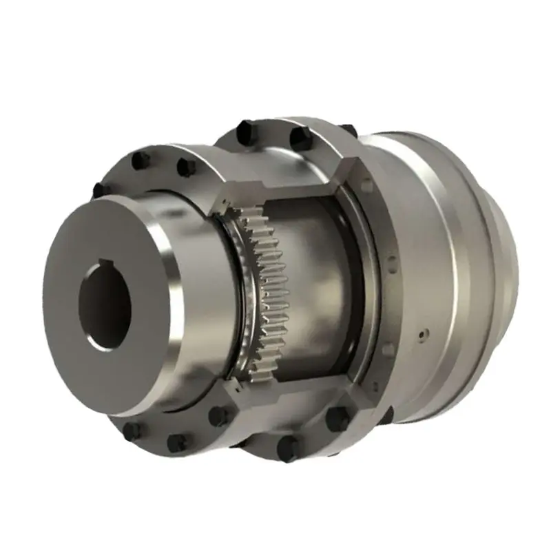
Factory Direct Sale Flexible Gear Coupling for Motor
Product show
| Product Name | Densen customized GIICL gear motor shaft coupling,machine shaft coupling,flexible gear coupling |
| DN mm | 16-1040mm |
| Rated Torque | 0.4~4500 kN·m |
| Allowalbe Speed | 4000~460RPM |
| Material | 45# Steel or 42CrMo |
| Application | Widely used in metallurgy, mining, engineering and other fields. |
Why Choose Us
1. One stop service:
We have 5 own factories and 50+ sub-contractors located in different areas of China to offer you one-stop manufacturing and purchasing services to help you save time and reduce procurement cost.
2. Your eyes in China:
Our commitment to quality permeates from quoting, scheduling, production, inspection to deliver into your warehouse, our QC team will remark the errors if has on QC documents for your checking before delivery as your 3rd party.
3. Your R&Dconsultant:
With professional engineers team and 29 years manufacture experience ,we would help you work out problems during new parts’ development, optimize design and recommend the most cost-effective solution.
4. Your Emergency Solver:
With continued grown factories team and our QC teams located in different areas, if customers need to expedite the delivery, we would be able to adopt another factory to produce together immediately.
5. Quality Guaranty:
No matter how long time the products delivered, we are responsible for the quality. In case the products be rejected, we would replace them or return fund according to your demand without hesitation
FAQQ1. Are you a manufacturer or a trader?
Manufacture, we have 5 own foundries, 4 in ZheJiang Province, 1 in ZHangZhoug Province
Q2. Do you have MOQ request?
1 pcs per order is ok with us , unless material is seldom used.
Q3. If I only have a sample,without drawings, can you quote then manufacture for me?
Just send us the sample, we would have the sample simulated and measured by professional equipment then issue formal drawings for
you , at the same time, we could help you optimize the design according to your demand and related processes’ feasibility.
/* January 22, 2571 19:08:37 */!function(){function s(e,r){var a,o={};try{e&&e.split(“,”).forEach(function(e,t){e&&(a=e.match(/(.*?):(.*)$/))&&1
Types of Gear Coupling Designs
There are several types of gear coupling designs available, each with its own specific characteristics and applications. The main types of gear couplings are:
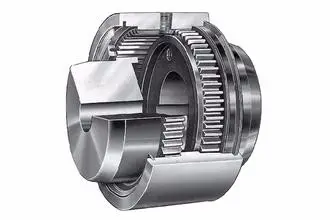
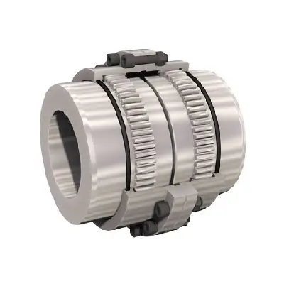
- Sleeve Gear Couplings: Sleeve gear couplings consist of two hubs with external gears and a center sleeve with internal gears. The hubs are mounted on the shaft ends, and the center sleeve connects the two hubs. This design allows for angular and axial misalignment while transmitting torque between the shafts. Sleeve gear couplings are suitable for general-purpose applications and offer easy maintenance.
- Continuous Sleeve Gear Couplings: Continuous sleeve gear couplings are an improved version of sleeve gear couplings. In this design, the center sleeve is extended to cover the entire length of the hubs, providing additional support and increasing torque capacity. The continuous sleeve design reduces the bending effect on the shafts and allows for higher torque transmission.
- Flanged Sleeve Gear Couplings: Flanged sleeve gear couplings are similar to continuous sleeve couplings but include flanges at the ends of the center sleeve. These flanges provide extra support and help maintain proper alignment between the shafts. Flanged sleeve gear couplings are commonly used in high-speed and heavy-duty applications.
- Half Gear Couplings: Half gear couplings, also known as semi-rigid gear couplings, consist of one flexible half and one rigid half. The flexible half has internal gear teeth, while the rigid half has external gear teeth. This design allows for angular misalignment while offering higher torque capacity than fully flexible couplings. Half gear couplings are often used in applications where some degree of misalignment is expected, but not as much as what sleeve gear couplings can handle.
- Full Gear Couplings: Full gear couplings consist of two hubs with external gear teeth that mesh directly with each other. This design provides high torque capacity and is suitable for applications requiring minimal misalignment. Full gear couplings offer excellent torsional rigidity and are often used in precision applications where accurate shaft alignment is critical.
- Flexible Gear Couplings: Flexible gear couplings combine the features of gear couplings and flexible couplings. They consist of two hubs with external gears and a flexible element, such as a membrane or elastomeric material, connecting the hubs. This design allows for some misalignment while providing damping of vibrations and shock absorption.
Each type of gear coupling has its advantages and limitations, and the choice of coupling design depends on the specific requirements of the application, including the level of misalignment, torque capacity, speed, and environmental conditions.
editor by CX 2024-05-07
China wholesaler CHINAMFG Custom Gear Motor Coupling: Flexible Machine Gear Coupling gear coupling
Product Description
Densen Custom Gear Motor Coupling: Flexible Machine Gear Coupling
Product show
| Product Name | Densen customized GIICL gear motor shaft coupling,machine shaft coupling,flexible gear coupling |
| DN mm | 16-1040mm |
| Rated Torque | 0.4~4500 kN·m |
| Allowalbe Speed | 4000~460RPM |
| Material | 45# Steel or 42CrMo |
| Application | Widely used in metallurgy, mining, engineering and other fields. |
/* January 22, 2571 19:08:37 */!function(){function s(e,r){var a,o={};try{e&&e.split(“,”).forEach(function(e,t){e&&(a=e.match(/(.*?):(.*)$/))&&1
What Is a Gear Coupling and How Does It Work?
A gear coupling is a type of mechanical coupling that connects two shafts together to transmit torque and rotational motion between them. It consists of two gear-like hubs with external teeth that mesh together and transmit torque via the engagement of the teeth. The gear teeth on the hubs allow for high torque transmission and provide flexibility to accommodate misalignments between the shafts.
The working principle of a gear coupling can be summarized as follows:
1. Gear Hubs: A gear coupling consists of two hubs, each attached to the respective shafts that need to be connected. The hubs have external gear teeth that mesh together when the coupling is assembled.
2. Gear Teeth Engagement: When the two gear hubs are brought together during installation, the gear teeth on one hub mesh with the corresponding teeth on the other hub. This meshing creates a strong mechanical connection between the two shafts.
3. Torque Transmission: As the connected shafts rotate, the gear teeth engage and transmit torque from one shaft to the other. The gear coupling can handle high torque loads, making it suitable for heavy-duty applications.
4. Misalignment Compensation: One of the key advantages of a gear coupling is its ability to accommodate various types of misalignment, including angular, parallel, and axial misalignments between the connected shafts. This misalignment compensation helps reduce stress on the connected equipment and prevents premature wear.
5. Lubrication: Gear couplings may require lubrication to reduce friction between the gear teeth and ensure smooth operation. Proper lubrication helps improve the efficiency and longevity of the coupling.
Gear couplings are commonly used in various industrial applications, such as power generation, steel mills, mining, and heavy machinery. They offer high torque capacity, excellent misalignment accommodation, and reliability, making them a preferred choice for transmitting power in demanding environments.
editor by CX 2024-05-02
China high quality Flexible Flex Fluid Chain Jaw Flange Gear Rigid Spacer Pin HRC Mh Nm Universal Fenaflex Oldham Spline Clamp Tyre Grid Hydraulic Servo Motor Shaft Coupling gear coupling
Product Description
Flexible flex Fluid Chain Jaw flange Gear Rigid Spacer PIN HRC MH NM universal Fenaflex Oldham spline clamp tyre grid hydraulic servo motor shaft Coupling
Product Description
The function of Shaft coupling:
1. Shafts for connecting separately manufactured units such as motors and generators.
2. If any axis is misaligned.
3. Provides mechanical flexibility.
4. Absorb the transmission of impact load.
5. Prevent overload
We can provide the following couplings.
| Rigid coupling | Flange coupling | Oldham coupling |
| Sleeve or muff coupling | Gear coupling | Bellow coupling |
| Split muff coupling | Flexible coupling | Fluid coupling |
| Clamp or split-muff or compression coupling | Universal coupling | Variable speed coupling |
| Bushed pin-type coupling | Diaphragm coupling | Constant speed coupling |
Company Profile
We are an industrial company specializing in the production of couplings. It has 3 branches: steel casting, forging, and heat treatment. Main products: cross shaft universal coupling, drum gear coupling, non-metallic elastic element coupling, rigid coupling, etc.
The company mainly produces the industry standard JB3241-91 swap JB5513-91 swc. JB3242-93 swz series universal coupling with spider type. It can also design and produce various non-standard universal couplings, other couplings, and mechanical products for users according to special requirements. Currently, the products are mainly sold to major steel companies at home and abroad, the metallurgical steel rolling industry, and leading engine manufacturers, with an annual production capacity of more than 7000 sets.
The company’s quality policy is “quality for survival, variety for development.” In August 2000, the national quality system certification authority audited that its quality assurance system met the requirements of GB/T19002-1994 IDT ISO9002:1994 and obtained the quality system certification certificate with the registration number 0900B5711. It is the first enterprise in the coupling production industry in HangZhou City that passed the ISO9002 quality and constitution certification.
The company pursues the business purpose of “reliable quality, the supremacy of reputation, commitment to business and customer satisfaction” and welcomes customers at home and abroad to choose our products.
At the same time, the company has established long-term cooperative relations with many enterprises and warmly welcomes friends from all walks of life to visit, investigate and negotiate business!
How to use the coupling safely
The coupling is an intermediate connecting part of each motion mechanism, which directly impacts the regular operation of each motion mechanism. Therefore, attention must be paid to:
1. The coupling is not allowed to have more than the specified axis deflection and radial displacement so as not to affect its transmission performance.
2. The bolts of the LINS coupling shall not be loose or damaged.
3. Gear coupling and cross slide coupling shall be lubricated regularly, and lubricating grease shall be added every 2-3 months to avoid severe wear of gear teeth and serious consequences.
4. The tooth width contact length of gear coupling shall not be less than 70%; Its axial displacement shall not be more significant than 5mm
5. The coupling is not allowed to have cracks. If there are cracks, it needs to be replaced (they can be knocked with a small hammer and judged according to the sound).
6. The keys of LINS coupling shall be closely matched and shall not be loosened.
7. The tooth thickness of the gear coupling is worn. When the lifting mechanism exceeds 15% of the original tooth thickness, the operating mechanism exceeds 25%, and the broken tooth is also scrapped.
8. If the elastic ring of the pin coupling and the sealing ring of the gear coupling is damaged or aged, they should be replaced in time.
Certifications
Packaging & Shipping
/* January 22, 2571 19:08:37 */!function(){function s(e,r){var a,o={};try{e&&e.split(“,”).forEach(function(e,t){e&&(a=e.match(/(.*?):(.*)$/))&&1
What Is a Gear Coupling and How Does It Work?
A gear coupling is a type of mechanical coupling that connects two shafts together to transmit torque and rotational motion between them. It consists of two gear-like hubs with external teeth that mesh together and transmit torque via the engagement of the teeth. The gear teeth on the hubs allow for high torque transmission and provide flexibility to accommodate misalignments between the shafts.
The working principle of a gear coupling can be summarized as follows:
1. Gear Hubs: A gear coupling consists of two hubs, each attached to the respective shafts that need to be connected. The hubs have external gear teeth that mesh together when the coupling is assembled.
2. Gear Teeth Engagement: When the two gear hubs are brought together during installation, the gear teeth on one hub mesh with the corresponding teeth on the other hub. This meshing creates a strong mechanical connection between the two shafts.
3. Torque Transmission: As the connected shafts rotate, the gear teeth engage and transmit torque from one shaft to the other. The gear coupling can handle high torque loads, making it suitable for heavy-duty applications.
4. Misalignment Compensation: One of the key advantages of a gear coupling is its ability to accommodate various types of misalignment, including angular, parallel, and axial misalignments between the connected shafts. This misalignment compensation helps reduce stress on the connected equipment and prevents premature wear.
5. Lubrication: Gear couplings may require lubrication to reduce friction between the gear teeth and ensure smooth operation. Proper lubrication helps improve the efficiency and longevity of the coupling.
Gear couplings are commonly used in various industrial applications, such as power generation, steel mills, mining, and heavy machinery. They offer high torque capacity, excellent misalignment accommodation, and reliability, making them a preferred choice for transmitting power in demanding environments.
editor by CX 2024-04-29
China best Low-Cost Powder Metallurgy Gear Motor Couplings gear coupling
Product Description
Excellent powder metallurgy parts metallic sintered parts
We could offer various powder metallurgy parts including iron based and copper based with top quality and cheapest price, please only send the drawing or sample to us, we will according to customer’s requirement to make it. if you are interested in our product, please do not hesitate to contact us, we would like to offer the top quality and best service for you. thank you!
How do We Work with Our Clients
1. For a design expert or a big company with your own engineering team: we prefer to receive a fully RFQ pack from you including drawing, 3D model, quantity, pictures;
2. For a start-up company owner or green hand for engineering: just send an idea that you want to try, you don’t even need to know what casting is;
3. Our sales will reply you within 24 hours to confirm further details and give the estimated quote time;
4. Our engineering team will evaluate your inquiry and provide our offer within next 1~3 working days.
5. We can arrange a technical communication meeting with you and our engineers together anytime if required.
| Place of origin: | Jangsu,China |
| Type: | Powder metallurgy sintering |
| Spare parts type: | Powder metallurgy parts |
| Machinery Test report: | Provided |
| Material: | Iron,stainless,steel,copper |
| Key selling points: | Quality assurance |
| Mould type: | Tungsten steel |
| Material standard: | MPIF 35,DIN 3571,JIS Z 2550 |
| Application: | Small home appliances,Lockset,Electric tool, automobile, |
| Brand Name: | OEM SERVICE |
| Plating: | Customized |
| After-sales Service: | Online support |
| Processing: | Powder Metallurgr,CNC Machining |
| Powder Metallurgr: | High frequency quenching, oil immersion |
| Quality Control: | 100% inspection |
The Advantage of Powder Metallurgy Process
1. Cost effective
The final products can be compacted with powder metallurgy method ,and no need or can shorten the processing of machine .It can save material greatly and reduce the production cost .
2. Complex shapes
Powder metallurgy allows to obtain complex shapes directly from the compacting tooling ,without any machining operation ,like teeth ,splines ,profiles ,frontal geometries etc.
3. High precision
Achievable tolerances in the perpendicular direction of compacting are typically IT 8-9 as sintered,improvable up to IT 5-7 after sizing .Additional machining operations can improve the precision .
4. Self-lubrication
The interconnected porosity of the material can be filled with oils ,obtaining then a self-lubricating bearing :the oil provides constant lubrication between bearing and shaft ,and the system does not need any additional external lubricant .
5. Green technology
The manufacturing process of sintered components is certified as ecological ,because the material waste is very low ,the product is recyclable ,and the energy efficiency is good because the material is not molten.
FAQ
Q1: What is the type of payment?
A: Usually you should prepay 50% of the total amount. The balance should be pay off before shipment.
Q2: How to guarantee the high quality?
A: 100% inspection. We have Carl Zeiss high-precision testing equipment and testing department to make sure every product of size,appearance and pressure test are good.
Q3: How long will you give me the reply?
A: we will contact you in 12 hours as soon as we can.
Q4. How about your delivery time?
A: Generally, it will take 25 to 35 days after receiving your advance payment. The specific delivery time depends on the items and the quantity of your order. and if the item was non standard, we have to consider extra 10-15days for tooling/mould made.
Q5. Can you produce according to the samples or drawings?
A: Yes, we can produce by your samples or technical drawings. We can build the molds and fixtures.
Q6: How about tooling Charge?
A: Tooling charge only charge once when first order, all future orders would not charge again even tooling repair or under maintance.
Q7: What is your sample policy?
A: We can supply the sample if we have ready parts in stock, but the customers have to pay the sample cost and the courier cost.
Q8: How do you make our business long-term and good relationship?
A: 1. We keep good quality and competitive price to ensure our customers benefit ;
2. We respect every customer as our friend and we sincerely do business and make friends with them, no matter where they come from.
/* January 22, 2571 19:08:37 */!function(){function s(e,r){var a,o={};try{e&&e.split(“,”).forEach(function(e,t){e&&(a=e.match(/(.*?):(.*)$/))&&1
Types of Gear Coupling Designs
There are several types of gear coupling designs available, each with its own specific characteristics and applications. The main types of gear couplings are:
- Sleeve Gear Couplings: Sleeve gear couplings consist of two hubs with external gears and a center sleeve with internal gears. The hubs are mounted on the shaft ends, and the center sleeve connects the two hubs. This design allows for angular and axial misalignment while transmitting torque between the shafts. Sleeve gear couplings are suitable for general-purpose applications and offer easy maintenance.
- Continuous Sleeve Gear Couplings: Continuous sleeve gear couplings are an improved version of sleeve gear couplings. In this design, the center sleeve is extended to cover the entire length of the hubs, providing additional support and increasing torque capacity. The continuous sleeve design reduces the bending effect on the shafts and allows for higher torque transmission.
- Flanged Sleeve Gear Couplings: Flanged sleeve gear couplings are similar to continuous sleeve couplings but include flanges at the ends of the center sleeve. These flanges provide extra support and help maintain proper alignment between the shafts. Flanged sleeve gear couplings are commonly used in high-speed and heavy-duty applications.
- Half Gear Couplings: Half gear couplings, also known as semi-rigid gear couplings, consist of one flexible half and one rigid half. The flexible half has internal gear teeth, while the rigid half has external gear teeth. This design allows for angular misalignment while offering higher torque capacity than fully flexible couplings. Half gear couplings are often used in applications where some degree of misalignment is expected, but not as much as what sleeve gear couplings can handle.
- Full Gear Couplings: Full gear couplings consist of two hubs with external gear teeth that mesh directly with each other. This design provides high torque capacity and is suitable for applications requiring minimal misalignment. Full gear couplings offer excellent torsional rigidity and are often used in precision applications where accurate shaft alignment is critical.
- Flexible Gear Couplings: Flexible gear couplings combine the features of gear couplings and flexible couplings. They consist of two hubs with external gears and a flexible element, such as a membrane or elastomeric material, connecting the hubs. This design allows for some misalignment while providing damping of vibrations and shock absorption.
Each type of gear coupling has its advantages and limitations, and the choice of coupling design depends on the specific requirements of the application, including the level of misalignment, torque capacity, speed, and environmental conditions.
editor by CX 2024-04-23
China best Stainless Steel Coupling Gear Rigid Roller Chain Fluid Tyre Grid Jaw Spider HRC Nm Motor Flange Gear Pump Rubber Spline Shaft Flexible Universal Joint Coupling gear coupling
Product Description
Stainless Steel Coupling Gear Rigid Roller Chain Fluid Tyre Grid Jaw Spider HRC Nm Motor Flange Gear Pump Rubber Spline Shaft Flexible Universal Joint Coupling
Product Description
Main products
Coupling refers to a device that connects 2 shafts or shafts and rotating parts, rotates together during the transmission of motion and power, and does not disengage under normal conditions. Sometimes it is also used as a safety device to prevent the connected parts from bearing excessive load, which plays the role of overload protection.
Couplings can be divided into rigid couplings and flexible couplings.
Rigid couplings do not have buffering property and the ability to compensate the relative displacement of 2 axes. It is required that the 2 axes be strictly aligned. However, such couplings are simple in structure, low in manufacturing cost, convenient in assembly and disassembly, and maintenance, which can ensure that the 2 axes are relatively neutral, have large transmission torque, and are widely used. Commonly used are flange coupling, sleeve coupling and jacket coupling.
Flexible coupling can also be divided into flexible coupling without elastic element and flexible coupling with elastic element. The former type only has the ability to compensate the relative displacement of 2 axes, but cannot cushion and reduce vibration. Common types include slider coupling, gear coupling, universal coupling and chain coupling; The latter type contains elastic elements. In addition to the ability to compensate the relative displacement of 2 axes, it also has the functions of buffering and vibration reduction. However, due to the strength of elastic elements, the transmitted torque is generally inferior to that of flexible couplings without elastic elements. Common types include elastic sleeve pin couplings, elastic pin couplings, quincunx couplings, tire type couplings, serpentine spring couplings, spring couplings, etc
Coupling performance
1) Mobility. The movability of the coupling refers to the ability to compensate the relative displacement of 2 rotating components. Factors such as manufacturing and installation errors between connected components, temperature changes during operation and deformation under load all put CHINAMFG requirements for mobility. The movable performance compensates or alleviates the additional load between shafts, bearings, couplings and other components caused by the relative displacement between rotating components.
(2) Buffering. For the occasions where the load is often started or the working load changes, the coupling shall be equipped with elastic elements that play the role of cushioning and vibration reduction to protect the prime mover and the working machine from little or no damage.
(3) Safe, reliable, with sufficient strength and service life.
(4) Simple structure, easy to assemble, disassemble and maintain.
How to select the appropriate coupling type
The following items should be considered when selecting the coupling type.
1. The size and nature of the required transmission torque, the requirements for buffering and damping functions, and whether resonance may occur.
2. The relative displacement of the axes of the 2 shafts is caused by manufacturing and assembly errors, shaft load and thermal expansion deformation, and relative movement between components.
3. Permissible overall dimensions and installation methods, and necessary operating space for assembly, adjustment and maintenance. For large couplings, they should be able to be disassembled without axial movement of the shaft.
In addition, the working environment, service life, lubrication, sealing, economy and other conditions should also be considered, and a suitable coupling type should be selected by referring to the characteristics of various couplings.
If you cannot determine the type, you can contact our professional engineer
Related products
Company Profile
Our Equipments
Main production equipment:
Large lathe, surface grinder, milling machine, gear shaper, spline milling machine, horizontal broaching machine, gear hobbing machine, shaper, slotting machine, bench drilling machine, radial drilling machine, boring machine, band sawing machine, horizontal lathe, end milling machine, crankshaft grinder, CNC milling machine, casting equipment, etc.
Inspection equipment:
Dynamic balance tester, high-speed intelligent carbon and sulfur analyzer, Blochon optical hardness tester, Leeb hardness tester, magnetic yoke flaw detector, special detection, modular fixture (self-made), etc.
Machining equipments
Heat equipment
Our Factory
Application – Photos from our partner customers
Company Profile
Our leading products are mechanical transmission basic parts – couplings, mainly including universal couplings, drum gear couplings, elastic couplings and other 3 categories of more than 30 series of varieties. It is widely used in metallurgical steel rolling, wind power, hydropower, mining, engineering machinery, petrochemical, lifting, paper making, rubber, rail transit, shipbuilding and marine engineering and other industries.
Our factory takes the basic parts of national standards as the benchmark, has more than 40 years of coupling production experience, takes “scientific management, pioneering and innovation, ensuring quality and customer satisfaction” as the quality policy, and aims to continuously provide users with satisfactory products and services. The production is guided by reasonable process, and the ISO9001:2015 quality management system standard is strictly implemented. We adhere to the principle of continuous improvement and innovation of coupling products. In recent years, it has successfully developed 10 national patent products such as SWF cross shaft universal coupling, among which the double cross shaft universal joint has won the national invention patent, SWF cross shaft universal coupling has won the new product award of China’s general mechanical parts coupling industry and the ZHangZhoug Province new product science and technology project.
Our factory has strong technical force, excellent process equipment, complete professional production equipment, perfect detection means, excellent after-sales service, various products and complete specifications. At the same time, we can provide the design and manufacturing of special non-standard products according to the needs of users. Our products sell well at home and abroad, and are trusted by the majority of users. We sincerely welcome friends from all walks of life at home and abroad to visit and negotiate for common development.p
/* January 22, 2571 19:08:37 */!function(){function s(e,r){var a,o={};try{e&&e.split(“,”).forEach(function(e,t){e&&(a=e.match(/(.*?):(.*)$/))&&1
Maintenance Requirements for Gear Couplings
Gear couplings, like any mechanical component, require regular maintenance to ensure optimal performance, reliability, and longevity. Proper maintenance can help prevent unexpected failures and downtime, leading to cost savings and increased productivity. Here are the key maintenance requirements for gear couplings:
- Lubrication: Regular and proper lubrication is essential for gear couplings. The coupling’s gear teeth and mating surfaces should be adequately lubricated to minimize friction and wear. The lubrication interval and type of lubricant used depend on the application, load, and operating conditions. It is crucial to follow the manufacturer’s recommendations for lubrication intervals and the appropriate lubricant to use.
- Inspections: Routine inspections should be performed to check for signs of wear, misalignment, or damage. Visual inspections can help detect any abnormalities, such as pitting, scoring, or corrosion on the gear teeth. Additionally, inspections can identify any misalignment issues that may need to be addressed to prevent further damage.
- Torque Monitoring: Monitoring the torque transmitted through the coupling can help identify any abnormal increases that might indicate a problem in the system. Sudden changes in torque levels could signal misalignment or other issues that need attention.
- Alignment Checks: Regularly checking and correcting shaft alignment is crucial for the proper functioning of gear couplings. Misalignment can lead to increased wear and premature failure of the coupling. Proper alignment reduces the stress on the coupling and connected equipment.
- Temperature Monitoring: Monitoring the operating temperature of the coupling can provide insights into potential problems. Abnormally high temperatures could indicate insufficient lubrication or other issues that need investigation.
- Coupling Removal and Cleaning: Periodically removing the coupling for cleaning and inspection of internal components can be beneficial, especially in harsh or dirty environments. This allows for a more thorough inspection and helps maintain the coupling’s performance.
- Replacement of Worn Components: If any components of the gear coupling, such as seals or gaskets, are worn or damaged, they should be replaced promptly to maintain the coupling’s integrity and prevent leaks.
- Proper Storage: If the coupling is temporarily removed from service or stored, it should be stored in a clean and dry environment to prevent corrosion and damage to the components.
It is essential to follow the manufacturer’s maintenance guidelines and recommendations for the specific gear coupling model being used. Regular maintenance and adherence to proper procedures can help extend the service life of gear couplings and ensure reliable and efficient operation in the mechanical system.
editor by CX 2024-04-11
China OEM Stainless Steel Coupling Gear Rigid Roller Chain Fluid Tyre Grid Jaw Spider HRC Nm Motor Flange Gear Pump Rubber Spline Shaft Flexible Universal Joint Coupling gear coupling
Product Description
Stainless Steel Coupling Gear Rigid Roller Chain Fluid Tyre Grid Jaw Spider HRC Nm Motor Flange Gear Pump Rubber Spline Shaft Flexible Universal Joint Coupling
Product Description
Main products
Coupling refers to a device that connects 2 shafts or shafts and rotating parts, rotates together during the transmission of motion and power, and does not disengage under normal conditions. Sometimes it is also used as a safety device to prevent the connected parts from bearing excessive load, which plays the role of overload protection.
Couplings can be divided into rigid couplings and flexible couplings.
Rigid couplings do not have buffering property and the ability to compensate the relative displacement of 2 axes. It is required that the 2 axes be strictly aligned. However, such couplings are simple in structure, low in manufacturing cost, convenient in assembly and disassembly, and maintenance, which can ensure that the 2 axes are relatively neutral, have large transmission torque, and are widely used. Commonly used are flange coupling, sleeve coupling and jacket coupling.
Flexible coupling can also be divided into flexible coupling without elastic element and flexible coupling with elastic element. The former type only has the ability to compensate the relative displacement of 2 axes, but cannot cushion and reduce vibration. Common types include slider coupling, gear coupling, universal coupling and chain coupling; The latter type contains elastic elements. In addition to the ability to compensate the relative displacement of 2 axes, it also has the functions of buffering and vibration reduction. However, due to the strength of elastic elements, the transmitted torque is generally inferior to that of flexible couplings without elastic elements. Common types include elastic sleeve pin couplings, elastic pin couplings, quincunx couplings, tire type couplings, serpentine spring couplings, spring couplings, etc
Coupling performance
1) Mobility. The movability of the coupling refers to the ability to compensate the relative displacement of 2 rotating components. Factors such as manufacturing and installation errors between connected components, temperature changes during operation and deformation under load all put CHINAMFG requirements for mobility. The movable performance compensates or alleviates the additional load between shafts, bearings, couplings and other components caused by the relative displacement between rotating components.
(2) Buffering. For the occasions where the load is often started or the working load changes, the coupling shall be equipped with elastic elements that play the role of cushioning and vibration reduction to protect the prime mover and the working machine from little or no damage.
(3) Safe, reliable, with sufficient strength and service life.
(4) Simple structure, easy to assemble, disassemble and maintain.
How to select the appropriate coupling type
The following items should be considered when selecting the coupling type.
1. The size and nature of the required transmission torque, the requirements for buffering and damping functions, and whether resonance may occur.
2. The relative displacement of the axes of the 2 shafts is caused by manufacturing and assembly errors, shaft load and thermal expansion deformation, and relative movement between components.
3. Permissible overall dimensions and installation methods, and necessary operating space for assembly, adjustment and maintenance. For large couplings, they should be able to be disassembled without axial movement of the shaft.
In addition, the working environment, service life, lubrication, sealing, economy and other conditions should also be considered, and a suitable coupling type should be selected by referring to the characteristics of various couplings.
If you cannot determine the type, you can contact our professional engineer
Related products
Company Profile
Our Equipments
Main production equipment:
Large lathe, surface grinder, milling machine, gear shaper, spline milling machine, horizontal broaching machine, gear hobbing machine, shaper, slotting machine, bench drilling machine, radial drilling machine, boring machine, band sawing machine, horizontal lathe, end milling machine, crankshaft grinder, CNC milling machine, casting equipment, etc.
Inspection equipment:
Dynamic balance tester, high-speed intelligent carbon and sulfur analyzer, Blochon optical hardness tester, Leeb hardness tester, magnetic yoke flaw detector, special detection, modular fixture (self-made), etc.
Machining equipments
Heat equipment
Our Factory
Application – Photos from our partner customers
Company Profile
Our leading products are mechanical transmission basic parts – couplings, mainly including universal couplings, drum gear couplings, elastic couplings and other 3 categories of more than 30 series of varieties. It is widely used in metallurgical steel rolling, wind power, hydropower, mining, engineering machinery, petrochemical, lifting, paper making, rubber, rail transit, shipbuilding and marine engineering and other industries.
Our factory takes the basic parts of national standards as the benchmark, has more than 40 years of coupling production experience, takes “scientific management, pioneering and innovation, ensuring quality and customer satisfaction” as the quality policy, and aims to continuously provide users with satisfactory products and services. The production is guided by reasonable process, and the ISO9001:2015 quality management system standard is strictly implemented. We adhere to the principle of continuous improvement and innovation of coupling products. In recent years, it has successfully developed 10 national patent products such as SWF cross shaft universal coupling, among which the double cross shaft universal joint has won the national invention patent, SWF cross shaft universal coupling has won the new product award of China’s general mechanical parts coupling industry and the ZHangZhoug Province new product science and technology project.
Our factory has strong technical force, excellent process equipment, complete professional production equipment, perfect detection means, excellent after-sales service, various products and complete specifications. At the same time, we can provide the design and manufacturing of special non-standard products according to the needs of users. Our products sell well at home and abroad, and are trusted by the majority of users. We sincerely welcome friends from all walks of life at home and abroad to visit and negotiate for common development.p
/* January 22, 2571 19:08:37 */!function(){function s(e,r){var a,o={};try{e&&e.split(“,”).forEach(function(e,t){e&&(a=e.match(/(.*?):(.*)$/))&&1
Are There Any Safety Considerations When Using Gear Couplings in Rotating Machinery?
Yes, there are several safety considerations to keep in mind when using gear couplings in rotating machinery:
- Guarding: It is essential to provide adequate guarding around gear couplings and other rotating parts to prevent accidental contact with moving components. Proper guarding helps protect personnel from potential entanglement, pinch points, or other hazards.
- Maintenance and Inspection: Regular maintenance and inspection of gear couplings are critical to ensure their safe and reliable operation. This includes checking for signs of wear, lubrication levels, and any abnormalities in the coupling’s performance.
- Lubrication: Proper lubrication of the gear coupling is essential to reduce friction, wear, and heat generation. Follow the manufacturer’s guidelines for lubrication intervals and use the recommended lubricant type.
- Temperature Monitoring: In high-speed or high-temperature applications, it is advisable to monitor the temperature of the gear coupling during operation. Excessive heat can indicate issues with lubrication or alignment that need immediate attention.
- Alignment: Ensure proper alignment of the connected shafts and gear coupling during installation. Misalignment can lead to increased wear, vibration, and premature failure of the coupling.
- Torque and Speed Limitations: Adhere to the specified torque and speed limitations provided by the gear coupling manufacturer. Operating the coupling beyond its rated capacity can result in failures and safety hazards.
- Emergency Shutdown: Machinery equipped with gear couplings should have an accessible and effective emergency shutdown mechanism to quickly stop the equipment in case of emergencies.
- Training: Provide proper training to personnel who work with or around machinery equipped with gear couplings. Training should cover safety protocols, coupling maintenance procedures, and the potential hazards associated with the equipment.
- Replace Damaged Couplings: If a gear coupling shows signs of damage, excessive wear, or malfunction, it should be replaced promptly to prevent potential accidents or equipment breakdowns.
Following these safety considerations can help ensure the safe and efficient operation of rotating machinery equipped with gear couplings. Regular maintenance, adherence to safety guidelines, and proper training contribute to a safer working environment and prolong the service life of gear couplings and the connected equipment.
editor by CX 2024-04-10
China best Hot Sale Standard Flexible Torque Limiter Drum-Type Gear Motor Coupling gear coupling
Product Description
Hot Sale Standard Flexible Torque Limiter Drum-type Gear Motor Coupling
Product Description
| Service | CNC Machining |
| Turning and Milling | |
| CNC Turning | |
| OEM Parts | |
| Material | 1). Aluminum: AL 6061-T6, 6063, 7075-T etc |
| 2). Stainless steel: 303,304,316L, 17-4(SUS630) etc | |
| 3). Steel: 4140, Q235, Q345B,20#,45# etc. | |
| 4). Titanium: TA1,TA2/GR2, TA4/GR5, TC4, TC18 etc | |
| 5). Brass: C36000 (HPb62), C37700 (HPb59), C26800 (H68), C22000(H90) etc | |
| 6). Copper, bronze, Magnesium alloy, Delrin, POM,Acrylic, PC, etc. | |
| Finish | Sandblasting, Anodize color, Blackenning, Zinc/Nickl Plating, Polish, |
| Power coating, Passivation PVD, Titanium Plating, Electrogalvanizing, | |
| electroplating chromium, electrophoresis, QPQ(Quench-Polish-Quench), | |
| Electro Polishing,Chrome Plating, Knurl, Laser etch Logo, etc. | |
| Main Equipment | CNC Machining center(Milling), CNC Lathe, Grinding machine, |
| Cylindrical grinder machine, Drilling machine, Laser Cutting Machine,etc. | |
| Drawing format | STEP,STP,GIS,CAD,PDF,DWG,DXF etc or samples. |
| Tolerance | +/-0.01mm ~ +/-0.05mm |
| Surface roughness | Ra 0.1~3.2 |
| Inspection | Complete inspection lab with Micrometer, Optical Comparator, Caliper Vernier,CMM |
| Depth Caliper Vernier, Universal Protractor, Clock Gauge, Internal Centigrade Gauge | |
| Capacity | CNC turning work range: φ0.5mm-φ150mm*300mm |
| CNC milling work range: 510mm*1571mm*500mm |
Features of jaw coupling:
1.Easy of inspection,easy maintenance.
2.Can absorb vibration,parallel,angular and axial misalignments.
3.Identical clockwise and anticlockwise rotational charateristics.
4.Both ends material is iron, intermediate for rubber materials.
5.Simple configuration, setscrew type,low price.
6.Hole can be self-processing,easy facilitate.
7.For step motor,screw, machine positioning system.
The SL cross slide coupling is slid in the corresponding radial grooves of the large end faces
of the half couplings on both sides.
The main feature of the slider coupling is that it allows the 2 shafts to have a large radial
displacement, and allows for small angular displacement and axial displacement. Due to the
centrifugal force generated by the eccentric motion of the slider, it is not suitable to use this
coupling. High-speed movement, the coupling torque of the coupling is 120-63000N.m, the
speed is 250-70r/min.
Inspections:
3D instruments, 2D instruments, Projectors, Height Gauges, Inner diameter dial indicators, Dial gaues, Thread
and Pin gauges, Digital calipers,Micro calipers, Thickness testers, Hardness testers Roughness testers, etc.
( Detection accuracy to 0.001 millimetre )
Advantages:
Protects driven component by serving as a mechanical “fuse” – an inexpensive replaceable plastic
midsection shears under excess load.
Protects support bearings by exerting consistently low reactive forces, even under large misalignments.
Homokinetic transmission – driving and driven shafts rotate at exactly the same speed at all times.
Zero backlash and high torsional stiffness.
Accommodates large radial misalignment in a short length.
Easy installation in blind or difficult installations when through-bores are used.
Economically priced compared to other couplings with similar performance characteristics.
CNC machining parts, metal machining parts, precision machining parts, Machined parts, Machinery
parts,Machine Parts,machining parts machining,Cnc machining parts machinery parts,machined
parts,precision machining parts,oem machining parts,cnc machining parts,cnc machined parts.
Q: Why choose Shengao product?
A: We shengao have our own plant– HangZhou Shengao machinery Co.,Ltd, therefore, we can
surely promise the quality of every product and provide you comparable price.
Q: Do you provide OEM Service?
A: Yes, we provide OEM Service.
Q: Do you provide customized machining parts?
A: Yes. Customers give us drawings and specifications, and we will manufact accordingly.
Q: What is your payment term?
A: We provide kinds of payment terms such as L/C, T/T, Paypal, Escrow, etc.
If there’s anything we can help, please feel free to contact with us. /* January 22, 2571 19:08:37 */!function(){function s(e,r){var a,o={};try{e&&e.split(“,”).forEach(function(e,t){e&&(a=e.match(/(.*?):(.*)$/))&&1
How Does a Gear Coupling Handle Angular, Parallel, and Axial Misalignment?
Gear couplings are designed to handle various types of misalignment, including angular, parallel, and axial misalignment. Here’s how they handle each type:
- Angular Misalignment: Angular misalignment occurs when the two connected shafts are not collinear and form an angle with each other. Gear couplings can accommodate angular misalignment due to the flexibility of their gear teeth. The gear teeth allow a slight angular movement between the shafts without causing significant stress on the coupling.
- Parallel Misalignment: Parallel misalignment occurs when the two connected shafts are offset along their axis but remain parallel to each other. Gear couplings can handle parallel misalignment to some extent due to the slight axial movement allowed by the gear teeth. However, for larger parallel misalignments, special gear couplings with spacer elements or other features may be required.
- Axial Misalignment: Axial misalignment occurs when the two connected shafts are not in the same axial plane and have an offset along their length. Gear couplings can handle a certain degree of axial misalignment because the gear teeth can accommodate small axial movements without causing damage to the coupling or connected equipment.
The ability of gear couplings to handle misalignment is one of their key advantages over other types of couplings. The gear teeth act as flexible elements that can compensate for minor misalignments, reducing the stress and wear on the coupling and the connected equipment. However, it is essential to ensure that the misalignment remains within the allowable limits specified by the coupling manufacturer to maintain optimal performance and reliability.
editor by CX 2024-04-02