Product Description
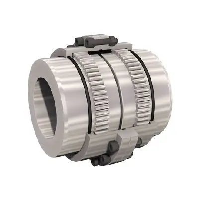
GFC-80X114 Manufacturer Flexible Clamp Style GFC Shaft Spider Gear Motor Jaw Coupling
GFC-80X114 Manufacturer Flexible Clamp Style GFC Shaft Spider Gear Motor Jaw Coupling
| model parameter | common bore diameter d1,d2 | ΦD | L | LF | LP | F | M | tightening screw torque (N.M) |
| GFC-14X22 | 3,4,5,6,6.35 | 14 | 22 | 14.3 | 6.6 | 5.0 | M2.5 | 1.0 |
| GFC-20×25 | 3,4,5,6,6.35,7,8,9,9.525,10 | 20 | 25 | 16.7 | 8.6 | 5.9 | M3 | 1.5 |
| GFC-20X30 | 3,4,5,6,6.35,7,8,9,9.525,10 | 20 | 30 | 19.25 | 8.6 | 5.9 | M3 | 1.5 |
| GFC-25X30 | 4,5,6,6.35,7,8,9,9.525,10,11,12 | 25 | 30 | 20.82 | 11.6 | 8.5 | M4 | 2.5 |
| GFC-25X34 | 4,5,6,6.35,7,8,9,9.525,10,11,12 | 25 | 34 | 22.82 | 11.6 | 8.5 | M4 | 2.5 |
| GFC-30×35 | 5,6,6.35,7,8,9,10,11,12,12.7,14,15,16 | 30 | 35 | 23 | 11.5 | 10 | M4 | 2.5 |
| GFC-30X40 | 5,6,6.35,7,8,9,10,11,12,12.7,14,15,16 | 30 | 40 | 25 | 11.5 | 10 | M4 | 2.5 |
| GFC-40X50 | 6,8,9,10,11,12,12.7,14,15,16,17,18,19,20,22,24 | 40 | 50 | 32.1 | 14.5 | 14 | M5 | 7 |
| GFC-40X55 | 6,8,9,10,11,12,12.7,14,15,16,17,18,19,20,22,24 | 40 | 55 | 34.5 | 14.5 | 14 | M5 | 7 |
| GFC-40X66 | 6,8,910,11,12,12.7,14,15,16,17,18,19,20,22,24 | 40 | 66 | 40 | 14.5 | 14 | M5 | 7 |
| GFC-55X49 | 10,11,12,12.7,14,15,16,17,18,19,20,22,24,25,28,30,32 | 55 | 49 | 32 | 16.1 | 13.5 | M6 | 12 |
| GFC-55X78 | 8,10,12,12.7,14,15,16,17,18,19,20,22,24,25,28,30,32 | 55 | 78 | 46.4 | 16.1 | 19 | M6 | 12 |
| GFC-65X80 | 14,15,16,17,18,19,20,22,24,25,28,30,32,35,38,40 | 65 | 80 | 48.5 | 17.3 | 14 | M8 | 20 |
| GFC-65X90 | 14,15,16,17,18,19,20,22,24,25,28,30,32,35,38,40 | 65 | 90 | 53.5 | 17.3 | 22.5 | M8 | 20 |
| GFC-80X114 | 19,20,22,24,25,28,30,32,35,38,40,42,45 | 80 | 114 | 68 | 22.5 | 16 | M8 | 20 |
| GFC-95X126 | 19,20,22,24,25,28,30,32,35,38,40,42,45,50,55 | 95 | 126 | 74.5 | 24 | 18 | M10 | 30 |
| model parameter | Rated torque (N.M)* |
allowable eccentricity (mm)* |
allowable deflection angle (°)* |
allowable axial deviation (mm)* |
maximum speed rpm |
static torsional stiffness (N.M/rad) |
moment of inertia (Kg.M2) |
Material of shaft sleeve | Material of shrapnel | surface treatment | weight (g) |
| GFC-14X22 | 5.0 | 0.1 | 1 | ±02 | 10000 | 50 | 1.0×10⁻⁶ | High strength aluminum alloy | Polyurethane imported from Germany | Anodizing treatment | 10 |
| GFC-20X25 | 5.0 | 0.1 | 1 | ±02 | 10000 | 50 | 1.0×10⁻⁶ | 15 | |||
| GFC-20X30 | 5.0 | 0.1 | 1 | ^02 | 10000 | 53 | 1.1×10⁻⁶ | 19 | |||
| GFC-25X30 | 10 | 0.1 | 1 | 10000 | 90 | 5.2X10⁻⁶ | 33 | ||||
| GFC-25X34 | 10 | 0.1 | 1 | £)2 | 10000 | 90 | 5.2×10⁻⁶ | 42 | |||
| GFC-30X35 | 12.5 | 0.1 | 1 | ±02 | 10000 | 123 | 6.2×10⁻⁶ | 50 | |||
| GFC-30×40 | 12.5 | 0.1 | 1 | 102 | 10000 | 123 | 6.2×10⁻⁶ | 60 | |||
| GFC-40X50 | 17 | 0.1 | 1 | 8000 | 1100 | 3.8×10⁻⁵ | 115 | ||||
| GFC-40X55 | 17 | 0.1 | 1 | ±02 | 8000 | 1100 | 3.8×10⁻⁵ | 127 | |||
| GFC-40X66 | 17 | 0.1 | 1 | 7000 | 1140 | 3.9×10⁻⁵ | 154 | ||||
| GFC-55X49 | 45 | 0.1 | 1 | ±02 | 6500 | 2350 | 1.6×10⁻³ | 241 | |||
| GFC-55X78 | 45 | 0.1 | 1 | 102 | 6000 | 2500 | 1.6×10⁻³ | 341 | |||
| GFC-65X80 | 108 | 0.1 | 1 | ±02 | 5500 | 4500 | 3.8×10⁻³ | 433 | |||
| GFC-65X90 | 108 | 0.1 | 1 | ±02 | 5500 | 4800 | 3.8×10⁻³ | 583 | |||
| GFC-80X114 | 145 | 0.1 | 1 | £)2 | 4500 | 5000 | 1.8×10⁻³ | 1650 | |||
| GFC-95X126 | 250 | 0.1 | 1 | ±02 | 4000 | 5000 | 2.0×10⁻³ | 1000 |
Types of Gear Coupling Designs
There are several types of gear coupling designs available, each with its own specific characteristics and applications. The main types of gear couplings are:
- Sleeve Gear Couplings: Sleeve gear couplings consist of two hubs with external gears and a center sleeve with internal gears. The hubs are mounted on the shaft ends, and the center sleeve connects the two hubs. This design allows for angular and axial misalignment while transmitting torque between the shafts. Sleeve gear couplings are suitable for general-purpose applications and offer easy maintenance.
- Continuous Sleeve Gear Couplings: Continuous sleeve gear couplings are an improved version of sleeve gear couplings. In this design, the center sleeve is extended to cover the entire length of the hubs, providing additional support and increasing torque capacity. The continuous sleeve design reduces the bending effect on the shafts and allows for higher torque transmission.
- Flanged Sleeve Gear Couplings: Flanged sleeve gear couplings are similar to continuous sleeve couplings but include flanges at the ends of the center sleeve. These flanges provide extra support and help maintain proper alignment between the shafts. Flanged sleeve gear couplings are commonly used in high-speed and heavy-duty applications.
- Half Gear Couplings: Half gear couplings, also known as semi-rigid gear couplings, consist of one flexible half and one rigid half. The flexible half has internal gear teeth, while the rigid half has external gear teeth. This design allows for angular misalignment while offering higher torque capacity than fully flexible couplings. Half gear couplings are often used in applications where some degree of misalignment is expected, but not as much as what sleeve gear couplings can handle.
- Full Gear Couplings: Full gear couplings consist of two hubs with external gear teeth that mesh directly with each other. This design provides high torque capacity and is suitable for applications requiring minimal misalignment. Full gear couplings offer excellent torsional rigidity and are often used in precision applications where accurate shaft alignment is critical.
- Flexible Gear Couplings: Flexible gear couplings combine the features of gear couplings and flexible couplings. They consist of two hubs with external gears and a flexible element, such as a membrane or elastomeric material, connecting the hubs. This design allows for some misalignment while providing damping of vibrations and shock absorption.
Each type of gear coupling has its advantages and limitations, and the choice of coupling design depends on the specific requirements of the application, including the level of misalignment, torque capacity, speed, and environmental conditions.


editor by CX 2023-08-17