1-0-0. p. 211. Retrieved 17 May 2-0-0. p. 86. Retrieved 30 January 2015. Green 1996, pp. 2337-2361 “ANSI G7 Standard Roller Chain – Tsubaki Europe”. Tsubaki Europe. Tsubakimoto Europe B.V. Retrieved 18 June 2. External links Wikimedia Commons has media related to Roller chains. The Complete Xihu (West Lake) Dis. to Chain Categories: Chain drivesMechanical power transmissionMechanical power control
Why Choose Us 1. Reliable Quality Assurance System 2. Cutting-Edge Computer-Controlled CNC Machines 3. Bespoke Solutions from Highly Experienced Specialists 4. Customization and OEM Available for Specific Application 5. Extensive Inventory of Spare Parts and Accessories 6. Well-Developed CZPT Marketing Network 7. Efficient After-Sale Service System
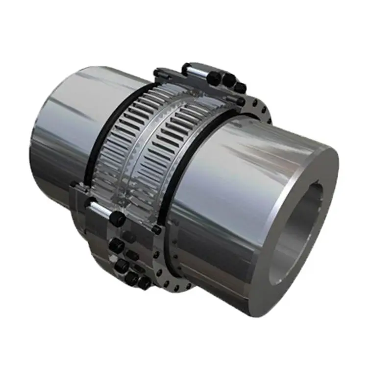
Materials Used in Manufacturing Gear Couplings
Gear couplings are designed to transmit torque between shafts while accommodating misalignment. To ensure the durability and reliability of gear couplings, manufacturers use a variety of materials, each with its specific properties. Commonly used materials in manufacturing gear couplings include:
Steel: Steel is the most widely used material for gear couplings. It offers excellent strength, durability, and resistance to wear and fatigue. Steel gear couplings are suitable for a wide range of applications, including heavy-duty industrial machinery.
Stainless Steel: Stainless steel is chosen for gear couplings that require resistance to corrosion and high-temperature environments. Stainless steel couplings are commonly used in food processing, pharmaceutical, and chemical industries.
Alloy Steel: Alloy steel is utilized to enhance specific properties, such as increased strength and improved performance under high loads and extreme conditions. Alloy steel gear couplings are ideal for demanding applications in heavy industries.
Cast Iron: Cast iron is known for its excellent machinability and good resistance to wear. Cast iron gear couplings are suitable for low to moderate torque applications and can be cost-effective in certain scenarios.
Non-Metallic Materials: In some cases, non-metallic materials like nylon or urethane may be used for specific gear coupling applications, especially in situations where electrical isolation or chemical resistance is required.
The choice of material depends on the application’s demands, including the torque, speed, environmental conditions, and budget considerations. Gear coupling manufacturers carefully select materials that will provide optimal performance and longevity while meeting the specific requirements of the intended application.
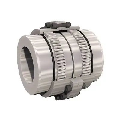
The Chain coupling is composed of a duplex roller chain and a pair of coupling sprockets. The function of connection and detachment is done by the joint of chain. It has the characteristic of compact and powerful, excellent durability, safe and smart, simple installation and easy alignment. The Xihu (West Lake) Dis.hua Chain coupling is suitable for a wide range of coupling applications.
Roller chain( Coupling Chains)
Though Hans Renold is credited with inventing the roller chain in 1880, sketches by Leonardo da Vinci in the 16th century show a chain with a roller bearing.Coupling chains)Coupling chains
Roller chain or bush roller chain is the type of chain drive most commonly used for transmission of mechanical power on many kinds of domestic, industrial and agricultural machinery, including conveyors, wire- and tube-drawing machines, printing presses, cars, motorcycles, and bicycles. It consists of a series of short cylindrical rollers held together by side links. It is driven by a toothed wheel called a sprocket. It is a simple, reliable, and efficient[1] means of power transmission.
Chain No.
Pitch
P
mm
Roller diameter
d1max mm
Width between inner plates b1min mm
Pin diameter
d2max mm
Pin length
Inner plate depth h2max mm
Plate thickness
Tmax mm
Transverse pitch Pt mm
Tensile strength
Qmin kN/lbf
Average tensile strength Q0 kN
Weight per piece q kg/pc
Lmax mm
Lcmax mm
4012
12.7-0-0. p. 211. Retrieved 17 May 2-0-0. p. 86. Retrieved 30 January 2015. Green 1996, pp. 2337-2361 “ANSI G7 Standard Roller Chain – Tsubaki Europe”. Tsubaki Europe. Tsubakimoto Europe B.V. Retrieved 18 June 2. External links Wikimedia Commons has media related to Roller chains. The Complete Xihu (West Lake) Dis. to Chain Categories: Chain drivesMechanical power transmissionMechanical power control
Why Choose Us 1. Reliable Quality Assurance System 2. Cutting-Edge Computer-Controlled CNC Machines 3. Bespoke Solutions from Highly Experienced Specialists 4. Customization and OEM Available for Specific Application 5. Extensive Inventory of Spare Parts and Accessories 6. Well-Developed CZPT Marketing Network 7. Efficient After-Sale Service System
Types of Gear Coupling Designs
There are several types of gear coupling designs available, each with its own specific characteristics and applications. The main types of gear couplings are:
Sleeve Gear Couplings: Sleeve gear couplings consist of two hubs with external gears and a center sleeve with internal gears. The hubs are mounted on the shaft ends, and the center sleeve connects the two hubs. This design allows for angular and axial misalignment while transmitting torque between the shafts. Sleeve gear couplings are suitable for general-purpose applications and offer easy maintenance.
Continuous Sleeve Gear Couplings: Continuous sleeve gear couplings are an improved version of sleeve gear couplings. In this design, the center sleeve is extended to cover the entire length of the hubs, providing additional support and increasing torque capacity. The continuous sleeve design reduces the bending effect on the shafts and allows for higher torque transmission.
Flanged Sleeve Gear Couplings: Flanged sleeve gear couplings are similar to continuous sleeve couplings but include flanges at the ends of the center sleeve. These flanges provide extra support and help maintain proper alignment between the shafts. Flanged sleeve gear couplings are commonly used in high-speed and heavy-duty applications.
Half Gear Couplings: Half gear couplings, also known as semi-rigid gear couplings, consist of one flexible half and one rigid half. The flexible half has internal gear teeth, while the rigid half has external gear teeth. This design allows for angular misalignment while offering higher torque capacity than fully flexible couplings. Half gear couplings are often used in applications where some degree of misalignment is expected, but not as much as what sleeve gear couplings can handle.
Full Gear Couplings: Full gear couplings consist of two hubs with external gear teeth that mesh directly with each other. This design provides high torque capacity and is suitable for applications requiring minimal misalignment. Full gear couplings offer excellent torsional rigidity and are often used in precision applications where accurate shaft alignment is critical.
Flexible Gear Couplings: Flexible gear couplings combine the features of gear couplings and flexible couplings. They consist of two hubs with external gears and a flexible element, such as a membrane or elastomeric material, connecting the hubs. This design allows for some misalignment while providing damping of vibrations and shock absorption.
Each type of gear coupling has its advantages and limitations, and the choice of coupling design depends on the specific requirements of the application, including the level of misalignment, torque capacity, speed, and environmental conditions.