Product Description
Product Description
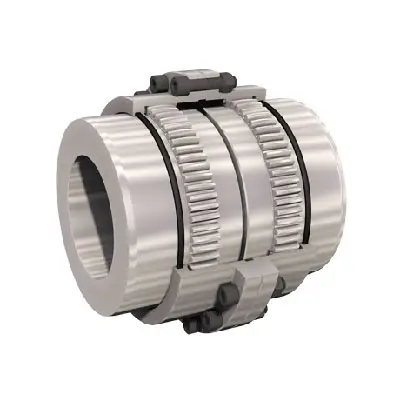
High Quality Drum Shaped Teeth Coupling
Drum shaped teeth coupling is a type of flexible coupling that is used to transmit torque between 2 shafts which are misaligned or need to be disconnected frequently. As the name implies, the coupling consists of a drum shaped element with teeth on the outer surface that mesh with corresponding teeth on the inner surface of a second drum. The flexibility of the coupling is achieved through the use of a resilient material, such as rubber or plastic, which is located between the 2 drums.
The drum shaped teeth coupling is an ideal solution where shock load and vibration are present in the system. The coupling can compensate for the relative displacement of the shafts, absorb shock loads, and prevent transmitting vibration. The drum shaped teeth coupling can also protect the machinery from damage caused by misalignment or human errors during installation and maintenance.
Key features of the drum shaped teeth coupling:
1. High torque capacity
2. Low backlash
3. Compact size
4. Easy to install
5. High misalignment capacity
6. Low maintenance
Applications of Bearing Bushings:
Drum shaped teeth coupling is a reliable and cost-effective solution for transmitting torque between misaligned shafts. Its flexible design can absorb shock loads, prevent transmitting vibration, and protect the machinery from damage. It is suitable for a wide range of applications, from power transmission to mining equipment. With its high torque capacity, low backlash, and compact size, the drum shaped teeth coupling is a preferred choice for many industries.
Company Profile
Our Company
HangZhou Metal Co., Ltd. (ASMT) serves in metallurgical (especial steel & aluminum), mining, mineral, cement etc. industry, integrating manufacturing, engineering, supply chain management, construction of package in domestic and abroad, international trade etc..
1. Pre-sales service:
To supply product application technological communication, drawing design, process design, test plan and packing and unloading plan.
2. In-sales service:
To supply production process report and inspection report.
To actively associate shipping with customers.
3. After-sales service:
To supply remote training instruction on in-site operation.
To supply solution to unexpected problem arising at user’s site.
To follow up product’s service life.
FAQ
1. What is the minimum order quantity for your products?
Our minimum order quantity varies depending on the product and material, but typically ranges from 100 to 500 pieces.
2. What materials do you work with?
We work with a wide range of materials, including steel, aluminum, brass, bronze, and iron. We also work with special alloys CZPT request.
3. Can you provide custom designs?
Yes, we specialize in providing custom designs based on your specific requirements. Our team of engineers can work with you to develop designs that meet your needs.
4. What is your production capacity?
Our production capacity varies depending on the product and material, but we have the capability to produce millions of pieces per year.
5. What is your lead time for orders?
Our lead time for orders varies depending on the product and quantity, but we typically require 4-6 weeks for production and delivery.
6. Do you offer quality control and testing?
Yes, we have strict quality control measures in place to ensure the highest level of quality for our products. We also offer testing services, including non-destructive testing, to ensure the integrity of our products.
7. What payment methods do you accept?
We accept various payment methods, including wire transfer, credit card, and PayPal. We can provide detailed payment terms CZPT request.
8. What is your return policy?
We have a comprehensive return policy that ensures customer satisfaction. If you are not satisfied with our products for any reason, please contact us and we will work with you to resolve the issue.
9. Do you offer international shipping?
Yes, we offer international shipping to customers worldwide. We can provide detailed shipping terms and pricing CZPT request.
10. How can I get a quote for my project?
Please contact us with your project specifications and 1 of our sales representatives will provide you with a quote within 48 hours. We look CZPT to the opportunity to work with you.
How Does a Gear Coupling Protect Connected Equipment from Shock Loads and Vibrations?
Gear couplings are designed to provide excellent protection to connected equipment from shock loads and vibrations, making them ideal for use in demanding and heavy-duty applications. The design and features of gear couplings that contribute to this protection include:
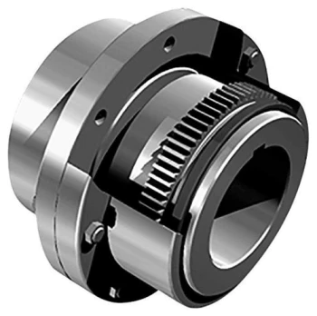
- Flexible and Rigid Elements: Gear couplings consist of two hubs with external gears that mesh together. Between these two hubs, there is a center sleeve with internal gear teeth. The center sleeve acts as a flexible element, while the outer hubs act as rigid elements. This combination allows the gear coupling to transmit torque while absorbing and dampening shock loads and vibrations.
- Misalignment Compensation: Gear couplings can accommodate angular, parallel, and axial misalignment between shafts. When the connected equipment experiences misalignment due to dynamic forces or shock loads, the gear coupling can flex and adjust to these changes, preventing excessive stress on the shafts and equipment.
- High Torsional Stiffness: Gear couplings offer high torsional stiffness, meaning they have minimal angular deflection under load. This stiffness helps maintain precise alignment and reduces the likelihood of damage to the connected equipment caused by misalignment-induced vibrations.
- Load Distribution: The toothed gear design of gear couplings ensures a large surface area of contact between the gears. This spreads the torque evenly across the gear teeth, resulting in a uniform distribution of load and reducing the concentration of stress on specific areas.
- Damping Characteristics: The flexible center sleeve in the gear coupling acts as a damping element that absorbs and dissipates vibrations, further protecting the connected equipment from harmful oscillations.
- High-Speed Balancing: Gear couplings are precisely balanced during manufacturing to minimize vibrations and ensure smooth operation even at high speeds. Proper balancing helps prevent resonances and reduces the impact of shock loads on the connected equipment.
By effectively absorbing and dampening shock loads and vibrations, gear couplings extend the life of the connected equipment and surrounding components, reduce maintenance requirements, and contribute to a more reliable and efficient mechanical system. However, it is essential to select the appropriate size and type of gear coupling based on the specific application and operating conditions to ensure optimal protection and performance.


editor by CX 2023-09-04
China Best Sales High Transmission Efficiency Quick Mounting Gear Coupling gear coupling
Product Description
Excellent powder metallurgy parts metallic sintered parts
We could offer various powder metallurgy parts including iron based and copper based with top quality and cheapest price, please only send the drawing or sample to us, we will according to customer’s requirement to make it. if you are interested in our product, please do not hesitate to contact us, we would like to offer the top quality and best service for you. thank you!
How do We Work with Our Clients
1. For a design expert or a big company with your own engineering team: we prefer to receive a fully RFQ pack from you including drawing, 3D model, quantity, pictures;
2. For a start-up company owner or green hand for engineering: just send an idea that you want to try, you don’t even need to know what casting is;
3. Our sales will reply you within 24 hours to confirm further details and give the estimated quote time;
4. Our engineering team will evaluate your inquiry and provide our offer within next 1~3 working days.
5. We can arrange a technical communication meeting with you and our engineers together anytime if required.
| Place of origin: | Jangsu,China |
| Type: | Powder metallurgy sintering |
| Spare parts type: | Powder metallurgy parts |
| Machinery Test report: | Provided |
| Material: | Iron,stainless,steel,copper |
| Key selling points: | Quality assurance |
| Mould type: | Tungsten steel |
| Material standard: | MPIF 35,DIN 3571,JIS Z 2550 |
| Application: | Small home appliances,Lockset,Electric tool, automobile, |
| Brand Name: | OEM SERVICE |
| Plating: | Customized |
| After-sales Service: | Online support |
| Processing: | Powder Metallurgr,CNC Machining |
| Powder Metallurgr: | High frequency quenching, oil immersion |
| Quality Control: | 100% inspection |
The Advantage of Powder Metallurgy Process
1. Cost effective
The final products can be compacted with powder metallurgy method ,and no need or can shorten the processing of machine .It can save material greatly and reduce the production cost .
2. Complex shapes
Powder metallurgy allows to obtain complex shapes directly from the compacting tooling ,without any machining operation ,like teeth ,splines ,profiles ,frontal geometries etc.
3. High precision
Achievable tolerances in the perpendicular direction of compacting are typically IT 8-9 as sintered,improvable up to IT 5-7 after sizing .Additional machining operations can improve the precision .
4. Self-lubrication
The interconnected porosity of the material can be filled with oils ,obtaining then a self-lubricating bearing :the oil provides constant lubrication between bearing and shaft ,and the system does not need any additional external lubricant .
5. Green technology
The manufacturing process of sintered components is certified as ecological ,because the material waste is very low ,the product is recyclable ,and the energy efficiency is good because the material is not molten.
FAQ
Q1: What is the type of payment?
A: Usually you should prepay 50% of the total amount. The balance should be pay off before shipment.
Q2: How to guarantee the high quality?
A: 100% inspection. We have Carl Zeiss high-precision testing equipment and testing department to make sure every product of size,appearance and pressure test are good.
Q3: How long will you give me the reply?
A: we will contact you in 12 hours as soon as we can.
Q4. How about your delivery time?
A: Generally, it will take 25 to 35 days after receiving your advance payment. The specific delivery time depends on the items and the quantity of your order. and if the item was non standard, we have to consider extra 10-15days for tooling/mould made.
Q5. Can you produce according to the samples or drawings?
A: Yes, we can produce by your samples or technical drawings. We can build the molds and fixtures.
Q6: How about tooling Charge?
A: Tooling charge only charge once when first order, all future orders would not charge again even tooling repair or under maintance.
Q7: What is your sample policy?
A: We can supply the sample if we have ready parts in stock, but the customers have to pay the sample cost and the courier cost.
Q8: How do you make our business long-term and good relationship?
A: 1. We keep good quality and competitive price to ensure our customers benefit ;
2. We respect every customer as our friend and we sincerely do business and make friends with them, no matter where they come from.
How Does a Gear Coupling Protect Connected Equipment from Shock Loads and Vibrations?
Gear couplings are designed to provide excellent protection to connected equipment from shock loads and vibrations, making them ideal for use in demanding and heavy-duty applications. The design and features of gear couplings that contribute to this protection include:
- Flexible and Rigid Elements: Gear couplings consist of two hubs with external gears that mesh together. Between these two hubs, there is a center sleeve with internal gear teeth. The center sleeve acts as a flexible element, while the outer hubs act as rigid elements. This combination allows the gear coupling to transmit torque while absorbing and dampening shock loads and vibrations.
- Misalignment Compensation: Gear couplings can accommodate angular, parallel, and axial misalignment between shafts. When the connected equipment experiences misalignment due to dynamic forces or shock loads, the gear coupling can flex and adjust to these changes, preventing excessive stress on the shafts and equipment.
- High Torsional Stiffness: Gear couplings offer high torsional stiffness, meaning they have minimal angular deflection under load. This stiffness helps maintain precise alignment and reduces the likelihood of damage to the connected equipment caused by misalignment-induced vibrations.
- Load Distribution: The toothed gear design of gear couplings ensures a large surface area of contact between the gears. This spreads the torque evenly across the gear teeth, resulting in a uniform distribution of load and reducing the concentration of stress on specific areas.
- Damping Characteristics: The flexible center sleeve in the gear coupling acts as a damping element that absorbs and dissipates vibrations, further protecting the connected equipment from harmful oscillations.
- High-Speed Balancing: Gear couplings are precisely balanced during manufacturing to minimize vibrations and ensure smooth operation even at high speeds. Proper balancing helps prevent resonances and reduces the impact of shock loads on the connected equipment.
By effectively absorbing and dampening shock loads and vibrations, gear couplings extend the life of the connected equipment and surrounding components, reduce maintenance requirements, and contribute to a more reliable and efficient mechanical system. However, it is essential to select the appropriate size and type of gear coupling based on the specific application and operating conditions to ensure optimal protection and performance.
editor by CX 2023-09-04
China best Custom Plastic POM Curved Toothed Gear, PA6 Spur Gear Coupling gear coupling
Product Description
Our Services
Product Design Material Selection
Mold Design Mold Making
Bulk Production Logo Printing
Surface Treatment Assembling
Packaging Door to Door Delivery
| Material | Nylon ,mc nylon, POM,ABS,PU,PP,PE,PTFE,UHMWPE,HDPE,LDPE, PVC,etc. |
| Color | Black, white, red, green, transparent or any color according to Pantone code |
| Size | As per customer’s requirements |
| Technology | Injection molding, CNC machining, Extrusion |
| Surface Treatment | Powder coating, Zinc coating, Galvanization, Electro-deposition coating, Chrome/zinc/nickel plating, Polishing, Silkscreen, Black oxide |
| Application | Automotive, ATV, Mechanical equipment, Construction, Home appliance, Aviation, Office facilities, Agriculture, etc. |
| Shippment | We have longterm cooperation with internation shipping agent and express company, so that shipping safty and arriving time are secured |
Detail Image
Why Choose Us
CZPT is a leading manufacture of OEM parts in rubber & plastic & metal parts. We are always pursuing providing better quality products in shorter period. With a knowledgeable team which has experience in molding and production, we are confident to help you develop and manufacture your product.
Our Machine
Customization Capabilities
Can Gear Couplings Accommodate High Torque and High-Speed Applications?
Yes, gear couplings are well-suited for high torque and high-speed applications in various industries. They are designed to transmit large amounts of torque efficiently while providing torsional rigidity and compensating for misalignment between shafts. The robust construction and unique toothed gear design of gear couplings allow them to handle heavy-duty and demanding operating conditions.
The key factors that enable gear couplings to accommodate high torque and high-speed applications are:
- Sturdy Construction: Gear couplings are typically made from high-quality materials such as steel or alloy, ensuring strength, durability, and the ability to withstand substantial torque loads without failure.
- High Torque Capacity: The toothed gear design of gear couplings allows for a large surface area of contact between the teeth, distributing torque evenly and effectively. This design significantly enhances the coupling’s torque-carrying capacity.
- Torsional Rigidity: Gear couplings offer excellent torsional rigidity, meaning they can resist angular deflection and maintain accurate torque transmission even under heavy loads and at high speeds.
- High-Speed Balancing: Gear couplings are precisely balanced during manufacturing to minimize vibration and prevent harmful effects on connected equipment, even when operating at high speeds.
- Misalignment Compensation: Gear couplings can accommodate both angular and parallel misalignment between shafts, which is common in high-speed applications where thermal expansion and dynamic forces come into play.
- Lubrication: Proper lubrication is crucial for reducing friction and wear in gear couplings, especially in high-speed applications where heat generation is higher. Lubrication also helps dissipate heat and ensures smooth operation.
Due to their ability to handle high torque and high speeds, gear couplings are commonly used in various industries, including steel, mining, power generation, paper mills, and more. However, it is essential to select the right size and type of gear coupling based on the specific application requirements and operating conditions to ensure optimal performance and reliability.
editor by CX 2023-08-15
China best Kc5018 Industrial Transmission Gear Reducer Conveyor Parts Chain Couplings gear coupling
Product Description
|
Chain |
Chain No. |
D Bore Dia | Dimension | Inertia
×10-3 kgf·m2 |
Approx Weight
kg |
Casing | ||||||||
| Min mm | Max mm | L
mm |
I
mm |
S
mm |
d1 mm |
d2 mm |
C
mm |
Dimension | Approx Weight
kg |
|||||
| A mm |
B mm |
|||||||||||||
| KC-5018 | 50-2X18 | 16 | 45 | 99.7 | 45.0 | 9.7 | 70 | 106 | 18.1 | 15.420 | 3.8 | 122 | 85 | 0.8 |
Chain couplings
The Chain coupling is composed of a duplex roller chain and a pair of coupling sprockets. The function of connection and detachment is done by the joint of chain. It has the characteristic of compact and powerful, excellent durability, safe and smart, simple installation and easy alignment. The Xihu (West Lake) Dis.hua Chain coupling is suitable for a wide range of coupling applications.
Roller chain( Coupling Chains)
Though Hans Renold is credited with inventing the roller chain in 1880, sketches by Leonardo da Vinci in the 16th century show a chain with a roller bearing.Coupling chains)Coupling chains
Roller chain or bush roller chain is the type of chain drive most commonly used for transmission of mechanical power on many kinds of domestic, industrial and agricultural machinery, including conveyors, wire- and tube-drawing machines, printing presses, cars, motorcycles, and bicycles. It consists of a series of short cylindrical rollers held together by side links. It is driven by a toothed wheel called a sprocket. It is a simple, reliable, and efficient[1] means of power transmission.
| Chain No. | Pitch
P mm |
Roller diameter
d1max |
Width between inner plates b1min mm |
Pin diameter
d2max |
Pin length | Inner plate depth h2max mm |
Plate thickness
Tmax |
Transverse pitch Pt mm |
Tensile strength
Qmin |
Average tensile strength Q0 kN |
Weight per piece q kg/pc |
||||||||||||||||||||||||||||||||||||||||||||||||||||||||||||||||||||||||||||||||||||||||||||||||||||||||||||||||||||||||||||||||||||||||||||||||||||||||||||||||||||||||||||||||||||||||||||||||||||||||||||||||||||||||||||||||||||||||||||||||||||||||||||||||||||||||||||||||||||||||||||||||||||||||||||||||||||||||||||||||||||||||||||||||||||||||||||||||||||||||||||||||||||||||||||||||||||||||||||||||||||||||||||||||||||||||||||||||||||||||||||||||||||||||||||||||||||||||||||||||||||||||||||||||||||||||||||||||||||||||||||||||||||||||||||||||||||||||||||||||||||||||||||||||||||||||||||||||||||||||||||||||||||||||||||||||||||||||||||||||||||||||||||||||||||||||||||||||||||||||||||||||||||||||||||||||||||||||||||||||||||||||||||||||||||||||||||||||||||||||||||||||||||||||||||||||||||||||||
| Lmax mm |
Lcmax mm |
||||||||||||||||||||||||||||||||||||||||||||||||||||||||||||||||||||||||||||||||||||||||||||||||||||||||||||||||||||||||||||||||||||||||||||||||||||||||||||||||||||||||||||||||||||||||||||||||||||||||||||||||||||||||||||||||||||||||||||||||||||||||||||||||||||||||||||||||||||||||||||||||||||||||||||||||||||||||||||||||||||||||||||||||||||||||||||||||||||||||||||||||||||||||||||||||||||||||||||||||||||||||||||||||||||||||||||||||||||||||||||||||||||||||||||||||||||||||||||||||||||||||||||||||||||||||||||||||||||||||||||||||||||||||||||||||||||||||||||||||||||||||||||||||||||||||||||||||||||||||||||||||||||||||||||||||||||||||||||||||||||||||||||||||||||||||||||||||||||||||||||||||||||||||||||||||||||||||||||||||||||||||||||||||||||||||||||||||||||||||||||||||||||||||||||||||||||||||||||||||||||
| 4012 | 12.7-0-0. p. 211. Retrieved 17 May 2-0-0. p. 86. Retrieved 30 January 2015. Green 1996, pp. 2337-2361 “ANSI G7 Standard Roller Chain – Tsubaki Europe”. Tsubaki Europe. Tsubakimoto Europe B.V. Retrieved 18 June 2. External links Wikimedia Commons has media related to Roller chains. The Complete Xihu (West Lake) Dis. to Chain Categories: Chain drivesMechanical power transmissionMechanical power control Why Choose Us
Types of Gear Coupling DesignsThere are several types of gear coupling designs available, each with its own specific characteristics and applications. The main types of gear couplings are:
Each type of gear coupling has its advantages and limitations, and the choice of coupling design depends on the specific requirements of the application, including the level of misalignment, torque capacity, speed, and environmental conditions.
China best High Precision Flexible Drum Gear Coupling coupling engineeringProduct Description
Drum Gear Coupling Shaft Coupling (GICL) Drum type coupling is just flexible coupling, coupling is made within the same number of ring gear and belt tooth flange half couplings and other parts. Divided into straight teeth and drum tooth outside 2 kinds of tooth profile, drum gear coupling Allows a larger angular displacement (as opposed to straight tooth coupling), can improve the tooth contact conditions, improve the ability to transfer torque, prolong service life.
Company Profile
HangZhou CZPT Machinery Manufacturing Co., Ltd. is a high-tech enterprise specializing in the design and manufacture of various types of coupling. There are 86 employees in our company, including 2 senior engineers and no fewer than 20 mechanical design and manufacture, heat treatment, welding, and other professionals. Advanced and reasonable process, complete detection means. Our company actively introduces foreign advanced technology and equipment, on the basis of the condition, we make full use of the advantage and do more research and innovation. Strict to high quality and operate strictly in accordance with the ISO9000 quality certification system standard mode. Our company supplies different kinds of products. High quality and reasonable price. We stick to the principle of “quality first, service first, continuous improvement and innovation to meet the customers” for the management and “zero defect, zero complaints” as the quality objective.
Our Services 1. Design Services 2. Product Services 3. Samples Procedure 4. Research & Development 5. Quality Control FAQ Q 1: Are you a trading company or a manufacturer? Q 2:Can you do OEM? Q 3:How long is your delivery time? Q 4: Do you provide samples? Is it free or extra? Q 5: How long is your warranty? Q 6: What is the MOQ? Q 7: Do you have inspection procedures for coupling? Q 8: Can I have a visit to your factory before the order? Q 9: What’s your payment? ♦Contact Us Web: huadingcoupling
Types of CouplingsA coupling is a device that connects two shafts and transmits power from one to the other. Its main purpose is to join two pieces of rotating equipment. It also allows for some degree of misalignment or end movement. Here are a few examples of coupling types: Beam coupling, Flexible coupling, Magnetic coupling, and Shaft coupling. Beam couplingBeam couplings are used to couple motors and other devices. They are available in several types, including flexible, slit, and rigid beam couplings. Each has unique properties and characteristics. These couplings are best for applications requiring a high level of precision and long life. They are also a practical solution for the connection of stepping and servo motors with screw rods. Flexible couplingA flexible coupling is a versatile mechanical connection that allows for the easy coupling of two moving parts. The design of these couplings allows for a variety of stiffness levels and can address a variety of problems, such as torsional vibrations or critical speed. However, there are a number of tradeoffs associated with flexible couplings. Magnetic couplingMagnetic coupling is a technique used to transfer torque from one shaft to another using a magnetic field. It is the most common type of coupling used in machinery. It is highly effective when transferring torque from a rotating motor to a rotating shaft. Magnetic couplings can handle high torques and high speeds. Shaft couplingA shaft coupling joins two shafts and transmits rotational motion. Generally, shaft couplings allow for some degree of misalignment, but there are also torque limiters. Selecting the right coupling can save you time and money and prevent equipment downtime. Here are the main features to consider when purchasing a coupling for your application. China Best Sales Industrial Worm Speed Gear Box Reducer Motor With Gearbox WXRV075 Input Shaft top gearWarranty: 1 year
Packaging & Shipping Safety Packing Method 1.Inside :Plastic bags with Chemical Desiccant For Gearboxes/Speed Reducer 2.Middle :Individual Carton packaging For Gearboxes/ Speed Reducer 3. Outside :Wooden Box For Gearboxes/ Speed Reducer FAQ FAQ: 1. Q: What’s type of your company. A: We are manufacturer.2. Q: what should I provide when I choose gearbox/speed reducer? A: 1) load condition 2) speed of rotation or speed ratio(combination with combine speed reducer can get extra low out putting rotational speed) 3) work circumstance(temperature, humidity,corrosion etc.) 4) space of installation3. Q: How long dose it take to finish my order? A: It depends on your quantity. Generally 25days for 1 20GP, Hollow Structure Helical Gearbox Positioning Rotary Gear box Table Transmission Planetary Speed Reducer 35days for 1 40HQ.4. Q: How can i know the process of my order? A: Detailed picture of the production process will be sent to you to confirm before shipping. Consummation QC system makes it possible to offer you reliable quality
Helical, Straight-Cut, and Spiral-Bevel GearsIf you are planning to use bevel gears in your machine, you need to understand the differences between Helical, Straight-cut, and Spiral bevel gears. This article will introduce you to these gears, as well as their applications. The article will also discuss the benefits and disadvantages of each type of bevel gear. Once you know the differences, you can choose the right gear for your machine. It is easy to learn about spiral bevel gears. Spiral bevel gearSpiral bevel gears play a critical role in the aeronautical transmission system. Their failure can cause devastating accidents. Therefore, accurate detection and fault analysis are necessary for maximizing gear system efficiency. This article will discuss the role of computer aided tooth contact analysis in fault detection and meshing pinion position errors. You can use this method to detect problems in spiral bevel gears. Further, you will learn about its application in other transmission systems. Hypoid bevel gearThe Hypoid bevel gear is similar to the spiral bevel gear but differs in the shape of the teeth and pinion. The smallest ratio would result in the lowest gear reduction. A Hypoid bevel gear is very durable and efficient. It can be used in confined spaces and weighs less than an equivalent cylindrical gear. It is also a popular choice for high-torque applications. The Hypoid bevel gear is a good choice for applications requiring a high level of speed and torque. Helical bevel gearCompared to helical worm gears, helical bevel gears have a small, compact housing and are structurally optimized. They can be mounted in various ways and feature double chamber shaft seals. In addition, the diameter of the shaft and flange of a helical bevel gear is comparable to that of a worm gear. The gear box of a helical bevel gear unit can be as small as 1.6 inches, or as large as eight cubic feet. Straight-cut bevel gearA straight-cut bevel gear is the easiest to manufacture. The first method of manufacturing a straight bevel gear was to use a planer with an indexing head. Later, more efficient methods of manufacturing straight bevel gears were introduced, such as the Revacycle system and the Coniflex system. The latter method is used by CZPT. Here are some of the main benefits of using a straight-cut bevel gear. Spur-cut bevel gearCZPT stocks bevel gears in spiral and straight tooth configurations, in a range of ratios from 1.5 to five. They are also highly remachinable except for the teeth. Spiral bevel gears have a low helix angle and excellent precision properties. CZPT stock bevel gears are manufactured using state-of-the-art technologies and know-how. Compared with spur-cut gears, these have a longer life span.
China supplier Custom Machining CNC Plastic Gear with Best SalesProduct Description
Custom Machining CNC Plastic Gear
FAQ: Q1: Where can I get product&price information? Q2: How soon can I get samples and how much the fee? Q3: How to enjoy the OEM services? Q4: Can you make machining parts based on our samples? Q5: Is it possible to know how are my products going on without visiting your company? Q6: Will my drawing safe after you get it?
Synthesis of Epicyclic Gear Trains for Automotive Automatic TransmissionsIn this article, we will discuss the synthesis of epicyclic gear trains for automotive automatic transmissions, their applications, and cost. After you have finished reading, you may want to do some research on the technology yourself. Here are some links to further reading on this topic. They also include an application in hybrid vehicle transmissions. Let’s look at the basic concepts of epicyclic gear trains. They are highly efficient and are a promising alternative to conventional gearing systems. Synthesis of epicyclic gear trains for automotive automatic transmissionsThe main purpose of automotive automatic transmissions is to maintain engine-drive wheel balance. The kinematic structure of epicyclic gear trains (EGTs) is derived from graph representations of these gear trains. The synthesis process is based on an algorithm that generates admissible epicyclic gear trains with up to ten links. This algorithm enables designers to design auto gear trains that have higher performance and better engine-drive wheel balance. ApplicationsThe epicyclic gear system is a type of planetary gear train. It can achieve a great speed reduction in a small space. In cars, epicyclic gear trains are often used for the automatic transmission. These gear trains are also useful in hoists and pulley blocks. They have many applications in both mechanical and electrical engineering. They can be used for high-speed transmission and require less space than other types of gear trains. CostThe cost of epicyclic gearing is lower when they are tooled rather than manufactured on a normal N/C milling machine. The epicyclic carriers should be manufactured in a casting and tooled using a single-purpose machine that has multiple cutters to cut the material simultaneously. This approach is widely used for industrial applications and is particularly useful in the automotive sector. The benefits of a well-made epicyclic gear transmission are numerous.
in Edmonton Canada sales price shop near me near me shop factory supplier 12V 24V 36V 48V DC Brushed Worm Gear Motor with Factory Price manufacturer best Cost Custom Cheap wholesaler
Far more importantly, we make special elements in accordance to supplied drawings/samples and warmly welcome OEM inquiries. we offer you one-cease solution for the obtain of mechanical electrical power transmission products in China. We have exported our products to Korea, Turkey, Bulgaria, Romania, Russia, Italy, Norway, the Usa, Canada, etc. 12V 24V 36V 48V DC Brushed Worm EPT EPT with Manufacturing unit Cost PG36M555 Series voltage: 3VDC 6VDC 9VDC 12VDC 24VDC
EPTT Introduction
in Imphal India sales price shop near me near me shop factory supplier Hot Sell Customized Performance Sintered Gear 40cr Spiral Bevel Gear manufacturer best Cost Custom Cheap wholesaler
a specialized provider of a total range of chains, sprockets, gears, gear racks, V-belts, couplings and reducers. The merchandise properly shows environmental safety and energy conserving. Hangzhou EPG Co.,Ltd. , was established in November, 1997. With its 5 wholly owned subsidiaries. Q:What`s the MOQ of your goods? A:one set,we can also deal with the sample order. and the massive-quantity. Q:How could i know if the merchandise suited for my EPTT? A:Our revenue will contact with you to make confident the particular dimensions,data and other EPTTant particulars of your aimed merchandise.We make positive all the goods match for your EPTT. Q:I want to locate a new supplier for items,can you? A:Confident,we can provide the EPTT day services for your consulting,we aim at being your most EPTTant provider. Q:What`s the payment terms of the order? A:As your necessity,we can accept several kinds of payment phrases.
in Cotonou Benin sales price shop near me near me shop factory supplier Helical Gear Gear Shaft Gear Ring Used for Forklift manufacturer best Cost Custom Cheap wholesaler
Our solution range also covers locking assemblies (clamping factors/locking system), taper bushes, QD bushes, bolt-on hubs, torque limiters, shaft collars, motor bases and motor slides, chain detachers, chain guides, common joint, rod finishes and yokes. Far more importantly, we make special elements in accordance to equipped drawings/samples and warmly welcome OEM inquiries. Wonderful consideration has been compensated on environmental security and vitality preserving. EPTcal EPT/EPT shaft/EPT ring used for forklift This set of EPTs is only a single part of the forklift,customed in accordance to custom’s drawing. one. Description
2. Images
three. OrEPTTprocess a. Consumer sends us the drawing or sample, If only sample, our company provide the CAD drawing. b. Our business supplies the processing method and quotation. c. Our company provides the sample right after customer verified processing method and quotation. d. Consumer locations the orEPTTafter verify the sample. e. Buyer pay 50% deposit f. EPTtity generation. g. Shell out the equilibrium soon after the acceptance and confirmation. h. Supply.
| ||||||||||||||||||||||||||||||||||||||||||||||||||||||||||||||||||||||||||||||||||||||||||||||||||||||||||||||||||||||||||||||||||||||||||||||||||||||||||||||||||||||||||||||||||||||||||||||||||||||||||||||||||||||||||||||||||||||||||||||||||||||||||||||||||||||||||||||||||||||||||||||||||||||||||||||||||||||||||||||||||||||||||||||||||||||||||||||||||||||||||||||||||||||||||||||||||||||||||||||||||||||||||||||||||||||||||||||||||||||||||||||||||||||||||||||||||||||||||||||||||||||||||||||||||||||||||||||||||||||||||||||||||||||||||||||||||||||||||||||||||||||||||||||||||||||||||||||||||||||||||||||||||||||||||||||||||||||||||||||||||||||||||||||||||||||||||||||||||||||||||||||||||||||||||||||||||||||||||||||||||||||||||||||||||||||||||||||||||||||||||||||||||||||||||||||||||||||||||||||||||||


